The art, science, and skill of designing for additive manufacturing (3D printing) are known as design for additive manufacturing (DfAM). In contrast to traditional manufacturing, this additive design technique enables engineers to produce production parts with more complex structures while using less weight and material. It represents a radical reversal of the way we often think about design. According to a recent poll by Jabil, approximately 60% of 3D printing stakeholders at businesses globally claimed that additive manufacturing had already altered the way they think and function. More design freedom, part consolidation, and time and money savings are all provided by using the DfAM technique.
With additive manufacturing, designers may think beyond standard design for manufacture and assembly restrictions. Unlike other production methods, AM offers unique geometric, material, and customizable benefits. The same is true for AM, which frequently results in anisotropic characteristics and may demand extensive post-processing. Due to AM’s advantages and downsides, it’s important to teach designers Additive Manufacturing design.
introduction
Design for manufacture and assembly (DFM) means designers should reduce manufacturing, assembly, and logistics costs while eliminating manufacturing difficulties. However, the capabilities of additive manufacturing technologies offer a chance to reconsider DFM to benefit from these technologies’ distinctive characteristics. AM technologies are now used for production manufacturing by many businesses. Siemens, Phonak, Widex, and other hearing aid manufacturers employ PBF, VPP, and MJT to make hearing device shells.
For the creation of molds for clear dental braces (also known as “aligners”), Align Technology utilizes stereolithography. GE and Boeing use metal PBF to make F-18 ducting and other parts. AM machines can generate millions of custom-designed dental aligners and hearing aids. AM technology offers low volume production, simple design modification integration, ideal geometries, and—most importantly—part reductions to simplify product assembly.
Design for Additive Manufacturing vs Design for Traditional Manufacturing
CNC milling design includes considering every operation and tool needed to make a product. A more complicated machine can create a difficult part more quickly, but they are more expensive. Some aspects of 3D printing design are process-dependent, and some are printer-dependent. A geometrically complex part is easy to make but requires a more complex machine and setup. 3D printing doesn’t require two procedures because the printer handles everything. There are many design options available, but there are also limitations that we must consider.
Basics Principles of DfAM
In the simplest terms, additive manufacturing design increases the possibility of building specific components.
Engineers frequently need to modify those parts to make existing parts compatible with additive manufacturing. There will always be some give and take. But by making smart changes and choosing the best material and process, you can often reach a good result.
Suppose you are familiar with the design standards for traditional manufacturing methods (such as injection molding or CNC machining). In that case, you should know the minimum wall thickness or hole size and material shrinkage criteria. However, additional design issues are exclusive only to 3D printing, such as part orientation, overhangs, and layer height.
To comprehend DfAM, imagine a design with thousands of discrete cross-sections or slices. Every technology for additive manufacturing does so by adding layers upon layers of material.
designing for additive manufacturing Methods
“Design for additive manufacturing”(DFAM) refers to “design for manufacturability” in “additive manufacturing” (AM). It refers to design methodologies or tools that improve functional performance and/or product life-cycle considerations utilizing additive manufacturing technologies. These key product life-cycle considerations include manufacturability, reliability, and cost.
This idea developed due to the tremendous amount of design freedom made available by AM technology. It is necessary to utilize DfAM procedures or tools to make the most of the one-of-a-kind capabilities AM processes offer. DfAM methodologies include topology optimization, design for multiscale structures (lattice or cellular structures), multi-material design, mass customization, and part consolidation.
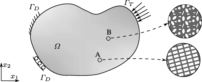
Topology optimization for DFAM
Topology optimization improves material placed inside a specified design region. The topology optimization can update a part’s size, shape, and topology, unlike size and shape optimization. Topology optimization creates complex optimal forms that are challenging to machine with CNC.
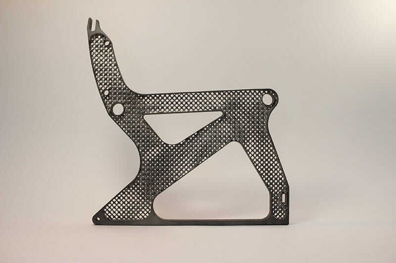
One solution we can fabricate through additive manufacturing technologies is a topology optimization outcome. During topology optimization, manufacturing constraints such smallest possible feature size must be considered. Topology optimization can help designers create the best and most suitable additive manufacturing complicated geometry.
Multiscale structure design
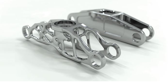
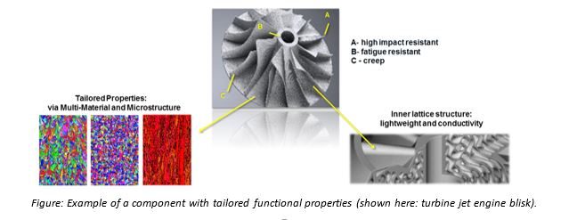
We can create Parts with multiscale complexities thanks to the one-of-a-kind capabilities offered by AM techniques. This ability allows designers to use micro or meso cellular or lattice structures to achieve the necessary features. For weight reduction, we can utilize lattice structures created by the AM technique in the aircraft industry. One of the purposes of biomedical implants, consisting of either lattice or cellular structures, is to enhance osseointegration.
Multi-material design for DFAM
Additive manufacturing technologies make it possible to create parts that have a distribution of multiple materials in complex patterns. Researchers provide Several design and simulation approaches to support the part’s design using various materials or Functionally Graded Materials. They developed These methods to assist designers in effectively using the benefits of additive manufacturing. These design methodologies present a challenge to conventional CAD systems as well. Now, most of them can only work with all the same materials.
Design for mass customization
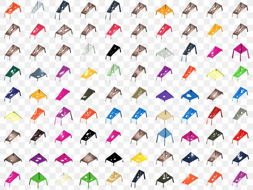
Because additive manufacturing can directly create parts from a digital product model, it greatly reduces the cost and the amount of time needed to produce customized goods. Therefore, the question of how to rapidly manufacture unique components becomes necessary for mass customization. They presented Several design strategies to assist designers or consumers in quickly obtaining a product that has been personalized to their preferences.
Parts consolidation
Some complex components are typically broken down into multiple sections so that we can manufacture more easily and assemble them more quickly. Because we know the traditional manufacturing methods have their limitations. The application of technologies for additive manufacturing has brought about a change in this circumstance. They carried out Case studies to demonstrate that several of the components of the initial design can be combined into a single, more complicated component and manufactured using additive manufacturing techniques.
An alternative term for this process of redesigning is “consolidation.” According to the research findings, consolidating parts will lower the total number of elements and increase the product’s functional performance. It is possible to classify as a subset of DfAM approaches the design methods that can direct designers toward the process of part consolidation.
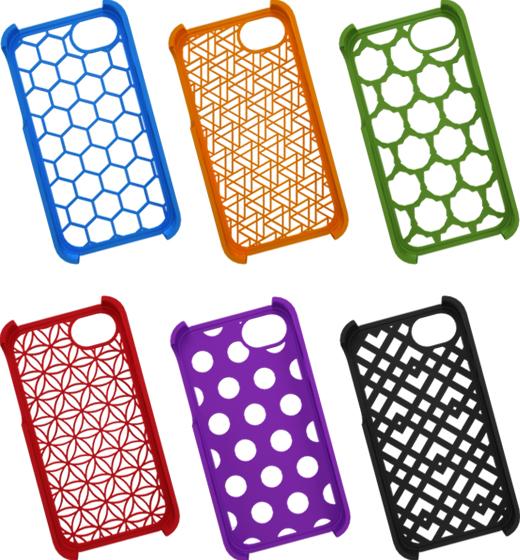
Lattice structures
One subclass of cellular structures is lattice structures (i.e., open). In the past, these structures were difficult to produce; therefore, there was not a significant amount of use for them. It is now possible to design and construct complicated forms because of the free-form manufacturing capacity offered by additive manufacturing technology. Lattice structures have mechanical qualities, including high strength, low mass, and multifunctionality. The aerospace and the biomedical sectors use these structures in their component parts. These lattice patterns approximate atomic crystal lattices, as discovered.
In this structure, the nodes represent atoms, and the struts represent atomic bonds. Meta-crystals are the name given to these structures. When they are deformed, they adhere to the principles of metallurgical hardening, which include grain boundary strengthening and precipitate hardening, among other things. Additionally, researchers reported that we could significantly increase the yield strength and ductility of the struts (meta-atomic bonds) by taking advantage of the non-equilibrium solidification phenomenon in Additive Manufacturing. These Found result in an improvement in the performance of the bulk structures.
Thermal issues in design for additive manufacturing
The temperature history inside the component during manufacture significantly impacts the process consistency and part quality for additive manufacturing (AM) techniques that employ heat to fuse powder or feedstock. This issue is genuine for metal AM techniques. In place of time-consuming and costly empirical testing, thermal modeling can guide the design of components and the selection of manufacturing process parameters.
design optimization for additive manufacturing
Additively built metallic objects with the same (macroscopic) shape and size but fabricated using different process settings have remarkably diverse microstructures, resulting in distinct mechanical properties. The plethora of available and extremely adjustable AM process parameters significantly impact the AM microstructures. Therefore, in theory, one could simultaneously 3D print the (macro-)structure and the desirable microstructure depending on the expected performance of the specific AM component under the available service load.
The design subspace is always a restricted portion of the overall design space. Depending on the thermo-chemo-mechanical service load, the performance, which is the objective of the design, may include multiple functional aspects. These operational aspects include specific energy absorption capacity, fatigue life/strength, high-temperature strength, creep resistance, erosion/wear resistance, and/or corrosion resistance. We believe that the optimal design approach is necessary for revealing the full potential of metal AM technologies and, as a result, for the widespread adoption of these technologies in manufacturing structurally critical load-bearing components.
The Principles of design for additive manufacturing
Although it is possible to utilize additive manufacturing to create a replica of an item that was initially manufactured using conventional techniques, doing so is not the most effective way to put additive manufacturing operate. Designating a product from the ground up with the specific opportunities and limitations of additive manufacturing is preferable. Doing so will allow you to get the most out of it in terms of performance, cost savings, and material utilization. Put another way, you should construct your product by adhering to the design principles for additive manufacturing, often known as DFAM.
Integrating process planning and product development is at the heart of design for manufacturability (DFM) and design for assembly and maintenance (DFAM). In contrast, DFAM analyzes competing elements to develop the most effective plan for production-grade manufacturing using additive technologies. Instead of optimizing a product for urethane casting or injection molding, this is done.
When employing DFAM principles to design a part for industrial-grade quality while minimizing production costs, additive manufacturing is not as simple as hitting print. This is especially true when designing a part for additive manufacturing. However, the performance of the produced parts is comparable to that of traditionally manufactured parts, despite the fact that lead times are cut, tooling costs are eliminated, and design freedom is increased. Utilizing DFAM principles early in the product development process enables product design teams to improve their designs to maximize the benefits of additive manufacturing.
Think Additively
Because “conventional” production typically involves starting with a block of material and cutting away material from it, most engineers in today’s world think “subtractively.” Therefore, we need to take that concept and turn it on its head since, at this point, the fewer resources we utilize, the fewer dollars we spend, and the more time we save. When it comes to manufacturing, you need to think about things differently.
In conclusion, effective deployment of DfAM calls for technical expertise and a shift in mentality. Again, the transition from subtractive manufacturing to additive manufacturing is essentially what’s going on here.
Design for Orientation
How a component is positioned on the printing bed will, as a result, have some bearing on the final item. If your part, for example, is printed while it is laying on its side, it will give it great strength and accuracy. If, on the other hand, it is printed while it is laying flat, it will produce the quickest print, and if you print it standing up, it will have the best appearance but will be the part that is the weakest overall.
A maximum amount of communication between engineering and operations is required for a practical design for orientation. Operations are the people that are in charge of running the printers, and they are the ones who will know whether or not an angle is self-supporting. Because of this, Operations will need to communicate with the engineering department.
Contour Design
Because of contour designs, certain pieces can be printed with only one or two extrusion lines instead of the usual three. You can make some incredibly lightweight but sturdy pieces with those extrusion lines, such as wing features. One example of this would be an airplane.
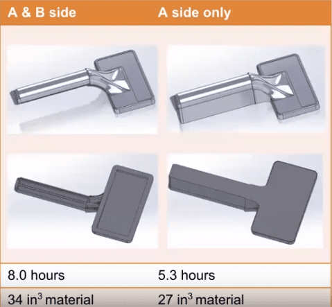
Segment and Bond Parts
What happens if you have an unprintable component due to its excessive size? However, we can segment the features by cutting the part into whatever sections will fit in the printer and then bonding them together. Some people believe they need to develop another manufacturing method, but we can segment the parts instead. One piece of advice that can be given to you about this is to use dovetail joints. Various software programs can assist you with this, and using dovetail joints will guarantee that your cut and joint are the strongest possible.
There are advantages to be gained from segmenting parts that can be printed without being cut up. On the other hand, significant time and material savings may be achieved if the component were first split into a few different parts and then printed individually.
Take note: you must make sure that this does not end up becoming a conventional kind of design for the assembling process. Customers segmenting parts nearly to the point of absurdity is something I’ve observed quite frequently, eliminating some of the benefits. Therefore, when conducting that kind of segmentation, you should exercise caution and ensure that you do not go above what is necessary.
Add Hardware
The addition of hardware can be done using a wide variety of different kinds of components. For instance, if you have problems with parts getting too hot or becoming too abrasive, you can add bushings to the regions struggling with contact problems.
If you are attempting to perform threading, I think you should avoid printing them because there are more effective ways to do it. One of these options is to employ heated inserts or Heli-Coils; by doing so, you will be able to incorporate metal threads into your 3D-printed part, making it suitable for long-term use.
There are always some quick ways to put in some locating features so that you can quickly snap and glue it in. If you have any magnets, rods, or other fixtures that you want to put into a part, there are always some quick ways to put them in there.
Minimize Complications
This theory is somewhat intriguing because it runs against the fundamental belief that “the less material we have, the better.” Suppose you are printing your component using FDM technology, which necessitates the use of support material, and your part looks like the one illustrated below. In that case, the handle part will have support material embedded. Because each layer in the model needs to switch from model to support, printing support material adds considerable time to the process. However, if we get rid of the support material, we can increase the time it takes for our prints.
Therefore, if you are trying to improve a component or have trouble printing a part, do not print the entire part unless it is necessary. Iterate only the portions of the part that are giving you trouble. For instance, if you’re having a locking portion of a part break off, and that’s the only portion having issues, don’t keep reprinting that part over and over again; instead, concentrate on the tab features and the correct orientation.
Critical Surface Treatment
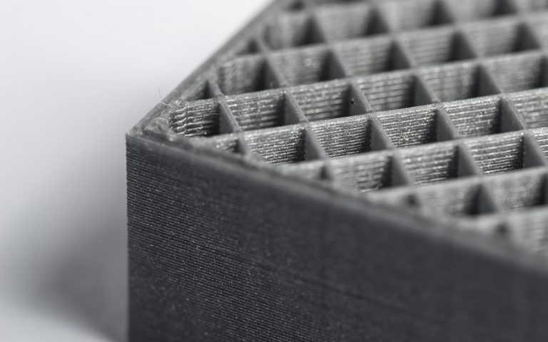
Metal additive manufacturing is a field that is fast increasing due to its capacity to create parts with precise geometries and customizable features for a wide variety of applications. This ability has led to the field’s rapid expansion. Despite this, the surface quality of these parts in their as-built configuration is almost always inadequate and unacceptable. The surface’s staircase effect, which is caused by the layer-by-layer nature of the deposition techniques, partially fused feedstock material, balling effects, spatter, or inadequate fusion, all contribute to the surface’s noticeably irregular morphology.
Surface imperfections and defects also contribute to the staircase effect. This high surface roughness can significantly deteriorate the performance of the additively manufactured parts, which imposes a substantial limit on their prospective applications. For example, these surface defects can affect fatigue performance, wear and scratch resistance, dimensional accuracy, and aesthetical aspects. In recent years, a significant amount of time and energy has been invested in the research and development of post-treatments that can improve the surface quality of metallic components that were additively built.
The single most critical factor to consider when designing for additive manufacturing
None of these standards address one of the most significant barriers to switching to production-grade additive manufacturing, which is a skills deficit in the area of additive manufacturing product design. Because of this gap, the most critical design guideline is to link yourself with additive manufacturing product design professionals from the beginning of any DFAM project. This should be done to ensure that your project is successful. They will suggest alterations to the product’s design to improve its cost efficiency and overall performance. In addition, they will be aware of how to improve operational efficiencies throughout the supply chain by utilizing on-demand production and virtual warehousing. When considering a transfer to additive manufacturing, the sooner you incorporate experienced AM design and engineering help, the bigger the potential benefits you stand to reap from the switch.