Sheet lamination is additive manufacturing (AM) technique in which layer glues together thin sheets of material to produce a single component that can then be cut into a 3D item. Laminated object manufacture (LOM) and ultrasonic consolidation (UC) are sheet lamination techniques. It can laminate sheets of paper, polymer, and metal, but each requires a different method of adhesion. We often pre-apply the paper sheets with a coating of activated adhesive activated with heat and pressure.
The same application of heat and pressure melts the sheets together for some polymers. Instead of melting or sintering, it joined metal sheets using ultrasonic vibrations under pressure (also known as ultrasonic welding).
Manufacturers employ sheet lamination as a rapid and low-cost means to 3D print non-functional prototypes, casting molds, and other basic designs out of readily handled materials, even though it is one of the less accurate AM processes. We also used sheet lamination to manufacture composite materials since it switched construction ingredients out in the middle of printing.
History of sheet lamination
Students had restricted access to one of two Stratasys material extrusion equipment and one 3D System vat photopolymerization device in the late 1990s. The systems were prohibitively expensive to purchase, and the materials were much more so, making the third option — a Helisys Laminated Object Manufacturing (LOM) system — even more appealing. LOM was the first commercially accessible sheet lamination method for additive manufacturing, debuting in the early 1990s. Because components were manufactured by pasting sheets of paper together layer by layer, it was also one of the cheapest AM methods at the time.
When you think about it, the concept isn’t so absurd. The layer resolution is reasonable because the paper is around 0.1 mm thick, and it was superior to material extrusion technologies on the market at the time. You didn’t need a high-power laser to sinter plastic or fuse metal since the paper is easy to cut or score with a laser. Granted, you won’t be making many functioning end-use components out of paper, but why not employ an inexpensive and quick procedure for visual aids and “fit-and-form” prototypes?
Sheet lamination is no longer exclusive to paper after three decades. The worldwide standards body ASTM defines the procedure as “an additive manufacturing process in which sheets of material are bonded to build an part.” Ultrasonic welding allows companies like Fabrisonic to attach metal sheets to produce a 3D object, allowing them to blend incompatible materials to construct functionally graded structures, create internal cooling channels in systems, and insert electronics or sensors into a part. The “stack-then-cut” technique for sheet lamination involves bonding sheets together and forming shapes.
How Sheet Lamination works
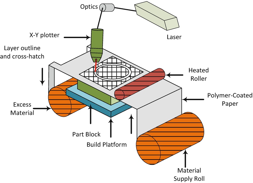
Although the underlying idea is the same, each form of sheet lamination operates somewhat differently. The original laminated item production technology, which was the first marketed additive manufacturing technique in 1991, is depicted schematically in the image below.
The material is first fed from the roller or deposited onto the construction platform in a thin sheet. Depending on sheet lamination, the following layer may or may not be bound to the preceding sheet. SDL and UAM glue the layers together before cutting the 3D shape, whereas CAM-LEM cuts the layers into shape before bonding them. This technique repeatedly creates layers until it has completed all of them and achieved the entire height. The print block is then removed, along with the undesired exterior borders, revealing the created 3D item.
The layer thickness in sheet lamination is the same as the thickness of thin sheets of material, and it determines the final quality. Equipment and procedures used determine the thickness of the layers.
Sheet Lamination – Step by Step
- On the cutting bed, it positions the material.
- We use the adhesive to adhere the material to the last layer.
- The necessary form is then laser or knife cut from the layer.
- Then comes the next layer.
- Reverse steps two and three, or cut the material before positioning it and bonding it.
Sheet Lamination technologies
Laminating (LOM)
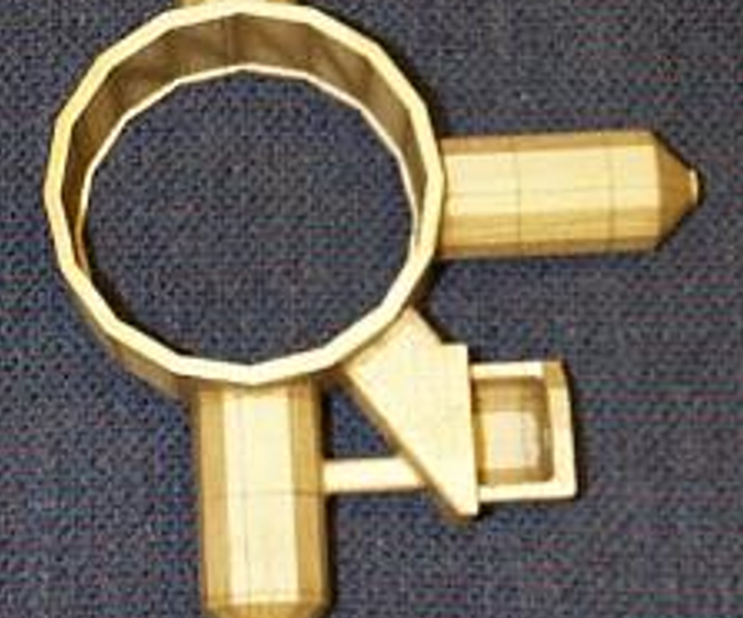
Laminating (LOM) is one of the earliest additive manufacturing processes to be developed, and it works with a range of sheet materials, including paper. Compared to alternative options, advantages include the use of A4 paper, which is widely available and affordable, as well as a straightforward and inexpensive setup.
Ultrasonic Additive Manufacturing (UAM)
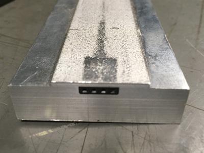
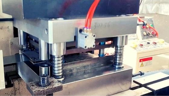
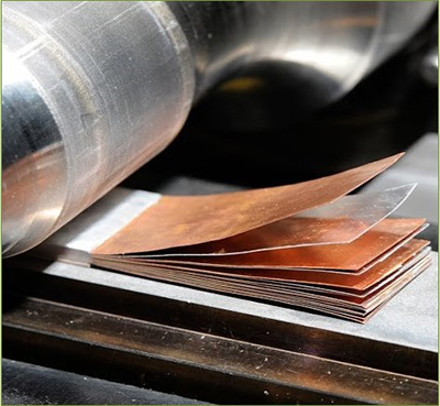
Ultrasonic welding joins together metal sheets in the Ultrasonic Additive Manufacturing (UAM) process. The metal that isn’t bound together must be CNC machined as part of the procedure. Unlike LOM, the hand can not easily remove the metal, necessitating machining to remove any undesired material. However, using 0.150mm thick and 25mm wide material-saving metallic tape results in less material to clip away afterward. Milling might occur before or after each layer is applied. Aluminum, copper, stainless steel, and titanium are just a few of the metals that have been employed.
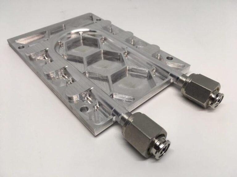
It may generate internal geometries with this low-temperature method. It uses Ultrasonic frequency and pressure to attach the metal, rather than melt it, which is one of the procedure’s significant advantages because it may connect a wide range of materials while using low energy (The Engineer, 2014). The most significant benefit of embedding electronics and cables is the ability to build overhanging (Karunakaran et al., 2012)—plastic deformation of metals assists in bonding materials. More surface contact is possible with plastic deformation, reinforcing existing connections (Janaki Ram et al., 2007).
post-processing
It must extract the portion from the surrounding sheet material during the post-processing procedure. Using cross hatching with LOM simplifies this procedure, but no special equipment is required because it uses paper, and the process is quick. Adding glue, paint, sanding, and further machining can improve the look of a part with poor structural quality.
How LOM works
Like other 3D-printed objects, LOM models start as CAD files. Before printing a model, 3D printing requires an STL or 3DS file format conversion from the original CAD file.
A set of feed rollers pulls A continuous sheet of material, such as plastic, paper, or (less typically), over a build platform in LOM equipment. They frequently applied adhesive to plastic and paper construction components. It moved a heated roller over a sheet of material on the build platform to melt its glue and press it into the platform, forming an item. It then sliced the material into the required design using a computer-controlled laser or blade. The laser also sliced any surplus material up in a crosshatch pattern, making it easier to remove after entirely creating the object.
Afterward, the build platform is lowered by about one-sixteenth of an inch, which is the thickness of one layer. After that, it dragged new material over the platform, and the hot roller passed over it once more, attaching the new layer to the one below it. It continued this procedure until it created the complete object.
printing process complete
When a part has completed “printing,” we take it from the building platform, eliminating any extra material. Objects printed on paper take on the appearance of wood and maybe sanded or polished as needed. It frequently coated paper things with paint or lacquer to keep moisture out. As you might expect, the bonding strength between layers determines the material qualities of items formed via sheet lamination. Within a layer, the material characteristics are usually the same as the feedstock used to manufacture the object (i.e., you are not melting the material as you do with powder-bed fusion processes).
This topic can cause some anisotropy in the vertical build direction, which may or may not be a problem depending on the part’s intended usage. It tasked one of my senior capstone design team teams to quickly prototype new upright designs and do “fit and form” tests on a student Formula One race vehicle that a larger group of students created. After 15 years, the same team can now employ laser-based powder-bed fusion to additively develop functional prototypes for “fit, form, and function” testing.
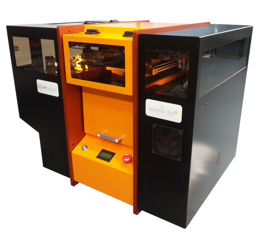
While Helisys is no longer in business, firms like Mcor still provide paper-based sheet laminating devices. Color is now a cost-effective alternative for paper-based sheet lamination, allowing customers to generate lifelike visual aids and full-color prototypes. Therefore sheet lamination is finding new applications in various sectors, including structural analysis, architecture, the visual arts, life sciences, education, and entertainment. Who knew that gluing and stacking colorful pieces of paper together could teach us so much?
compatibility of the materials
While sheet lamination is possible with a wide variety of materials, including paper, polymer, ceramic, and metal, each material has its binding process. The most common sheet lamination material is paper with a pre-applied adhesive layer activated with heat and pressure.
They used heat and pressure instead of glue in polymers. They’re melting together because they’re all on top of each other. Ultrasonic welding joins metal sheets together, while heat energy joins the base fibers and ceramics in the kiln together.
| Process | Material options |
| LOM | Papers |
| PSL | The majority of polymers |
| SLCOM | Fiberglass, carbon fiber, aramid fiber (i.e. Kevlar), PBO (i.e. Zylon), and metal fibers such as steel, aluminum, or titanium |
| CAM-LEM | Alumina Zirconia, zirconia-toughened alumina (ZTA), silica, and a range of oxide and non-oxide ceramics are among the other ceramics we may employ in our procedures. |
| SDL | Standard paper |
| CBAM | Fabrics have long fibers linked to thermoplastic matrix materials. Glass fiber with Nylon 12 and PEEK, and carbon fiber with Nylon 12 and PEEK. |
| UAM | Any material welded in a single component may be printed as a wide range of material combinations, allowing for property gradients and tailored material characteristics for improved performance. |
Usual application
Sheet lamination techniques are utilized for various applications and are closely related to the particular procedure. LOM and SDL processes create full-color prints on paper, whereas metal-based sheet lamination makes hybrid production. The SLCOM technique can create high-quality composite fiber components, while the CAM-LEM process may create ceramic parts.
Advantages and disadvantages of sheet lamination
Advantages of sheet lamination
- The printer will reduce printing time, but post-processing will be necessary.
- Integrability is a hybrid manufacturing system
- Material handling simplicity
- Parts made of ceramic (CAM-LEM) and composite fiber (SLCOM) are available.
- It can insert OEM components like sensors and wiring into the part during the layering step. The sheet lamination process and material used have a significant impact.
- Because they make it of ordinary materials, it is pretty inexpensive.
- There are no support structures required.
- More extensive work area than most today’s AM technology equipment
- Full-color printing — LOM/SDL can print in every rainbow color.
- The material condition does not change during or after several sheet lamination procedures.
- Layers of different materials are conceivable (UAM)
- Recycling cut material can sometimes be a drawback if the component is smaller than the sheet or bed size.
Disadvantages of sheet lamination
- It connected part resolution to sheet thickness along the vertical build axis because it cannot adjust layer height without altering sheet thickness.
- Several finishes are available depending on the paper or plastic used; however, some may require post-processing to create the desired look.
- There are just a few material possibilities available.
- Compared to other AM processes, removing extra material after the laminating step can be time-consuming and complex, creating a lot of waste.
- Some sheet lamination methods, such as “bind then shape,” make hollow pieces (internal voids and cavities) challenging to fabricate.
- The lamination process determines the bonding strength, and adhesive bonds are not always sufficient for long-term product strength and integrity.
- If the building part is smaller than the construction area or the sheet size, material waste might be substantial.
Main player
CAM-LEM Inc.
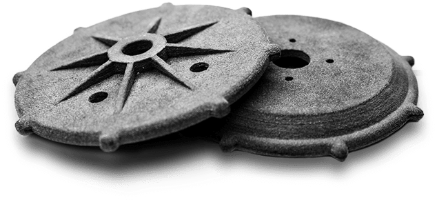
CAM-LEM Inc. (computer-aided manufacture of laminated engineering materials) specializes in microfluidic devices and applications and employs the sheet lamination technique to produce functional ceramic pieces. It created individual layers, then stacked and bonded together in this method, which exemplifies the “cut then stack” method of sheet limitation. Less material is needed to glue the layers together, restricting the geometries possible because the layers must stack on top of one another.
For example, suppose there is nothing underneath the layer to support the new layer and oppose gravity. In that case, it is impossible to build overhanging features with this technique to sheet lamination. The material underneath helps combat gravity in the “stack then cut” strategy, but it must be accessible to remove it after manufacturing. Indeed, one of the significant disadvantages of the stack then cut method is the amount of postprocessing required to chip away and remove the material that isn’t in the component.
anisotropy
As you might expect, the bonding strength between layers determines the material qualities of items formed via sheet lamination. Within a layer, the material characteristics are usually the same as the feedstock used to manufacture the object (i.e., you are not melting the material as you do with powder-bed fusion processes). This topic can cause some anisotropy in the vertical build direction, which may or may not be a problem depending on the part’s intended usage. It tasked one of my senior capstone design team teams to quickly prototype new upright designs and do “fit and form” tests on a student Formula One race vehicle that a larger group of students created (see Figure 1). After 15 years, the same team can now employ laser-based powder-bed fusion to additively develop functional prototypes for “fit, form, and function” testing.
While Helisys is no longer in business, firms like Mcor still provide paper-based sheet laminating devices. Color is now a cost-effective alternative for paper-based sheet lamination, allowing customers to generate lifelike visual aids and full-color prototypes. Therefore sheet lamination is finding new applications in various sectors, including structural analysis, architecture, the visual arts, life sciences, education, and entertainment. Who knew that gluing and stacking colorful pieces of paper together could teach us so much?
Refrence
- lboro.ac.uk
- plm.automation.siemens.com
- springer.com
- engineeringproductdesign.com
- additivemanufacturing.media
- livescience.com