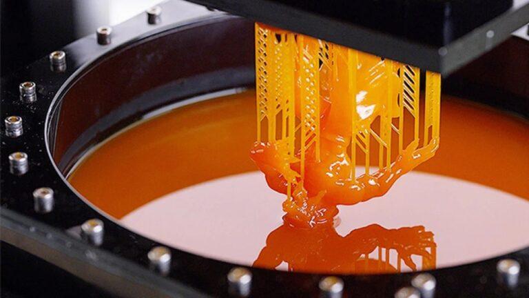
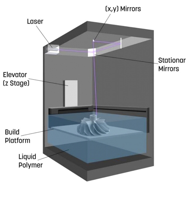
vat photopolymerization 3d printing or vat photopolymerization additive manufacturing uses a vat of liquid photopolymer resin, out of which layer constructs the model layer. An ultraviolet (UV) light cures or hardens the resin as needed, while a platform moves the object being created downwards after each successive layer has been cured. The technique involves using UV light to harden a thin coat of resin. The topic of this paper is the 3D printing of large models, which is not limited by the build volume of the printer.
Photopolymerization technologies employ liquid polymers that solidify when exposed to light. Photopolymerization is the name for this process, and photopolymers are liquids that photopolymerize. It is a widely used photopolymer in the coatings and printing sectors. Stereolithography was the first vat photopolymerization 3d printing (VPP) method, created by Charles Hull in his prior work with photopolymers.
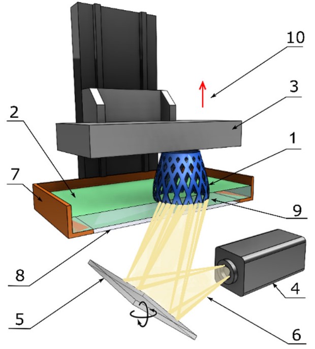
VPP entails repeatedly exposing a container (Vat) holding photopolymers to radiation patterns that match the part’s cross-sections. A UV laser delivered the radiation in the instance of stereolithography. We have used different radiation sources and stacking methods in subsequent VPP procedures. VPP techniques were among the earliest commercially available AM technologies, and We see these methods are used in various industries and applications nowadays.
Charles Boot developed vat polymerization in 1937. His company originally named the process “monomer liquid presentation,” but later changed it to “vat” as a ‘clever’ play on words.
How does vat photopolymerization 3d printing work?
vat photopolymerization additive manufacturing produces exceptional surface finishes by curing a liquid photopolymer resin one layer at a time with light. First, it lowered the build platform into the resin vat. Then, UV light from a laser or projector reacts within the resin. The photopolymer molecules link to form a solid, and the build platform moves away from the light source to build more layers. After it forms part, the machine drained of unused resin, and we remove the part.
photopolymerization – Step by Step
- It lowered the build platform by how much each layer is thick from the top of the resin tank.
- A UV light hardens the resin piece by piece. The platform keeps going down, and I build new layers on top of the ones that came before.
- Some machines use a blade that moves between layers to get a flat, smooth resin base to build on.
- Once the procedure is complete, the machine drains the resin from the vat and takes the object out.
Photopolymerization Printing Principle
A photopolymer, a light-curable resin, is held in a vat and exposed to visible or UV light during the process. The curing light is activated and stored in a vat before being exposed to visible or UV light. The curing light starts the curing process. A photopolymer, which is a light-curable resin, displays the polymerization reaction, which creates chains of polymers or crosslinks, is held in a vat and treated with either visible or UV light in the photopolymerization process. It triggered them to produce a solid resin by the curing light.
A solid resin comprises three photopolymer parts, as seen below in Figure. Monomers, oligomers, and photoinitiators are three components of the photopolymer combination, as depicted below in Figure. When exposed to curing light, monomers, oligomers, and photoinitiators undergo a polymerization process, resulting in polymer chains or crosslinks. Photoinitiators generate creative species that catalyze the chain creation necessary to make a solid resin. Three parts of the photopolymer photoinitiators, as stated below in Figure, emit creative species that act as catalysts for synthesizing monomers and oligomers.
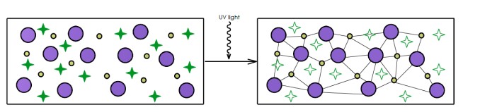
Between monomers and oligomers, the chain-forming chemical-thermal process is irreversible.
Monomers, oligomers, and photoinitiators are the chemical-thermal processes that build chains. Curing light can’t change prototypes back to liquid when put in it. This method cannot transform consecutive irreversible prototypes back to liquid form. Photoinitiators use this concept to release creative species that act as catalysts for resin chain formation layers gradually created from a sliced STL file. It manufactured successive resin layers from a cut STL file one by one.
Monomers and oligomers are both monomers and oligomers. The chemical-thermal chain-forming process is irreversible, and we cannot convert prototypes to liquid. Following this approach, it gradually manufactured successive resin layers from a sliced STL file.
most common vat photopolymerization 3D printing technologies
we classified Photopolymerization concerning the method of curing, which employ lasers (SLA), digital projection (digital light processing (DLP)), and light-emitting diodes (LEDs) and oxygen (continuous digital light processing (CDLP)/continuous liquid interface production (CLIP))
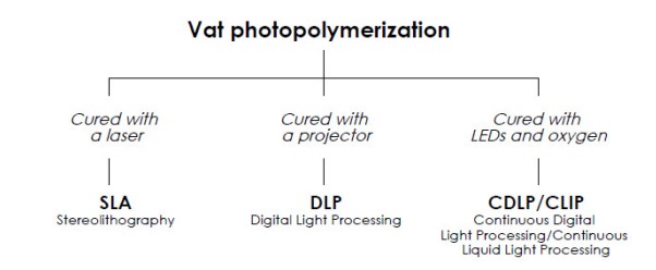
STEREOLITHOGRAPHY (SLA)
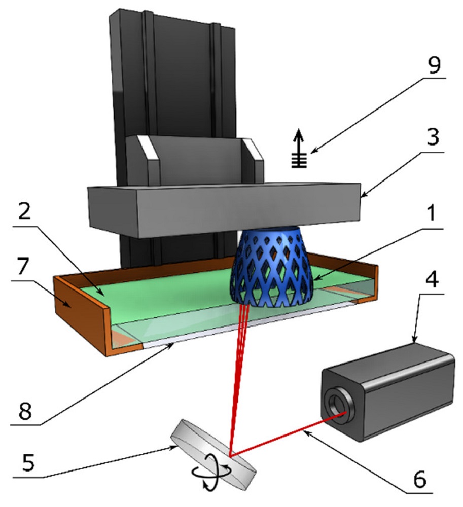
STEREOLITHOGRAPHY is a term used to describe a type of stereoscopic photography (SLA) During SLA, an ultraviolet laser placed within the vat photopolymerization 3d printing machine is targeted on the resin vat to layer by layer to create a component.
One of the most popular vat photopolymerization additive manufacturing processes is SLA. Researchers have developed a process that uses an ultraviolet (UV) laser beam to make items by layer-by-layer curing a polymer resin. Photosensitive thermoset polymers in liquid form are the materials used in SLA.
In 1986, the first 3D printing method, selective laser sintering, was patented. Even today, when items with high precision or a flawless surface finish are required, SLA remains the most cost-effective 3D printing method available. They got the best outcomes when the designer used the production process’s advantages and limits.
DIRECT LIGHT PROCESSING (DLP)
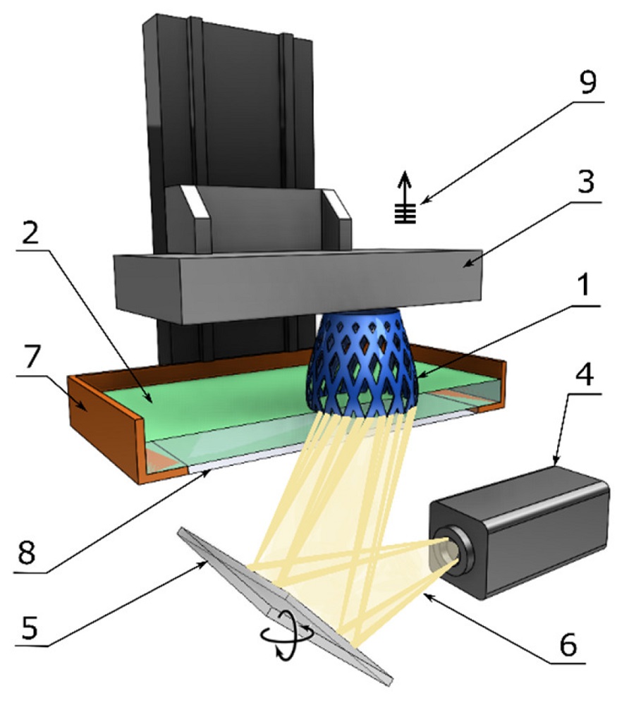
With one exception, DLP creates parts the same way as SLA does. Rather than employing a laser, this method uses a digital light projector screen that flashes a single picture of each layer of the part into the resin. As a result, it has sped the printing process up.
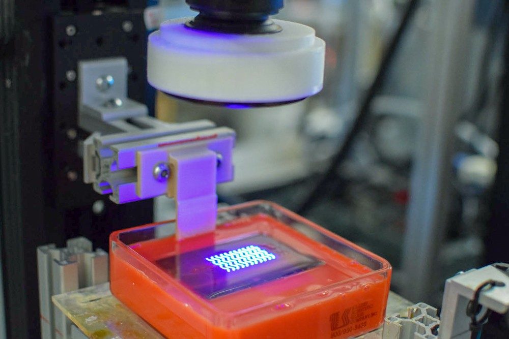
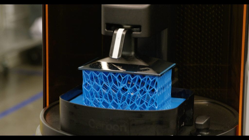
CARBON® DIGITAL LIGHT SYNTHESIS (DLS)
DLS is like DLP, but the build platform moves continuously rather than discretely near, thanks to a “dead zone” that prevents the part from curing to the projection window. Because the vat photopolymerization 3d printing process does not need to stop and detach the component from the build plate after each layer, DLS is even quicker than DLP.
Carbon DLS is a light and heat-based resin-based polymer process that produces components with isotropic characteristics, complicated shapes, and exceptional surface finishes. Engineers may manufacture end-use parts immediately off the printer with DLS’s wide variety of production-grade materials.
Two-Photon Lithography (2PL)
2PL is a direct laser-writing (DLW) method for creating 3D microstructures with a resolution below the diffraction limit using a laser beam. This process is made feasible by using the two-photon absorption (2PA) principle to polymerize a photosensitive polymeric substance, such as a (photo)resist. Because of its capacity to make solid polymer objects with a resolution of several nanometers, this technique has found a role in medical applications. Unlike traditional 3D printing, 2PL technology allows the solid polymer to cure freely in the resin vat, removing the requirement for layer-by-layer material deposition.
The uncured liquid resin is then removed from the printed portions using a suitable solvent. An ellipsoidal 3D point, also known as a voxel, is the minor polymer identity in 2PL 3D printing (volume pixel). The printing technique mentioned above applies to negative photoresists whose uncured portion dissolves in the solvent during postprocessing, but the cured part does not.
print parameters of SLA printing
In SLA systems, the manufacturer sets most print settings and cannot be changed. The layer height and portion orientation are the only inputs (the latter determines support location).
Layer height
The thickness of the layers varies between 25 and 100 microns. Lower layer heights capture curved geometries more precisely, but they increase build time and cost—as well as the risk of a faulty print. For most applications, a layer height of 100 microns is sufficient.
Build size
Another significant criterion for the designer is the build size. Depending on the type of machine, the size of the build is determined. The top-down orientation and the bottom-up orientation are the two primary SLA machine setups:
Top-down printers
They placed the laser source above the tank in top-down printers, creating the component looking upwards. The construction platform starts at the top of the resin vat and works down after each layer.
The light source is placed under the resin tank in bottom-up printers (see diagram above), creating the item upside down. The bottom of the tank is clear, with a silicone covering that allows the laser’s light to flow through while preventing the cured resin from clinging to it. As the construction platform goes upwards, it separates the cured resin from the bottom of the tank after each layer. We refer to this as the peeling process.
Bottom-up printers
The bottom-up direction is more common in desktop printers like Formlabs, whereas the top-down orientation is most common in industrial SLA systems. Bottom-up SLA printers are simpler to design and run, but they have a restricted build size. This limitation is because of the risk of the print failing due to the pressures exerted on the component during the peeling stage. Top-down printers can expand up to very high build sizes without sacrificing precision. These systems’ enhanced capabilities come at a higher price.
characteristics of SLA 3D printing
The essential support structure, curling, and layer adhesion are the fundamental characteristics of SLA 3D printing.
Structure of support
In SLA, a support structure is always necessary. It is possible to print support structures in the same material, and we must remove the product manually afterward. The part’s orientation determines the position and quantity of support. We should arrange the part so that aesthetically significant surfaces do not affect the support structures.
Bottom-up and top-down SLA printers use different support:
Support needs for top-down SLA printers are comparable to those for FDM. They’re required to print overhangs and bridges accurately (the critical overhang angle is usually 30). Any orientation is permissible for the part, and we commonly print parts flat to reduce the support and layer count.
SLA printers that print from the bottom up Support needs might be more complicated. We maintain Overhangs and bridges, but an essential requirement is to reduce the cross-sectional area of each layer: the pressures applied to the part during the peeling process may cause it to separate from the construction platform. These forces are proportionate to each layer’s cross-sectional area. As a result, we orientate pieces at an angle, and support reduction is not a significant problem.
Curling
Curling is one of the most severe SLA components in terms of precision. In FDM, curling is equivalent to warping. When exposed to the printer’s light source during the curing process, the resin shrinks significantly. When there is a significant amount of shrinkage, enormous internal tensions form between the new layer and the previously hardened material, causing the component to curl.
Support is necessary to assist in anchoring at-risk areas of a print to the build plate and reduce the chance of curling. It’s also crucial to keep parts oriented and huge flat layers to a minimum—Over-curing (for example, it can also cause curling by exposing the component to bright sunshine after printing).
During the design phase, keeping curling in mind is the most effective approach to avoid it. Avoid extensive thin and flat regions or create a framework to support the part from curling wherever workable.
Adhesion between layers
Mechanical characteristics of SLA printed items are isotropic. A single UV laser pass is insufficient to cure the liquid resin completely. Later laser passes to aid in the high-level fusion of previously cemented layers. Curing occurs long after it completes the printing process.
SLA products must be post-cured in a cure box under powerful UV light to acquire the finest mechanical qualities (and sometimes at elevated temperatures). This topic increases the SLA part’s toughness and temperature resistance, making it more brittle. The following are the implications of the post-curing process:
After curing, test samples of parts produced in conventional clear resin using a desktop SLA printer have nearly double the tensile strength (65 MPa compared to 38 MPa).
Parts may function at greater temperatures under load (maximum temperature of 58C vs. 42C).
At the interval, the elongation is almost half of what it is at the start (6.2 percent compared to 12 percent ).
Curing can also occur if we expose the SLA-printed object to the sun. Extended exposure to UV light hurts the physical properties and appearance of SLA parts—they may curl, become brittle, or change color. Before use, We highly recommend spray coating with clear UV acrylic paint because extended exposure to UV light hurts the physical properties and appearance of SLA parts—they may curl, become brittle, or change color.
Materials and applications for vat photopolymerization additive manufacturing
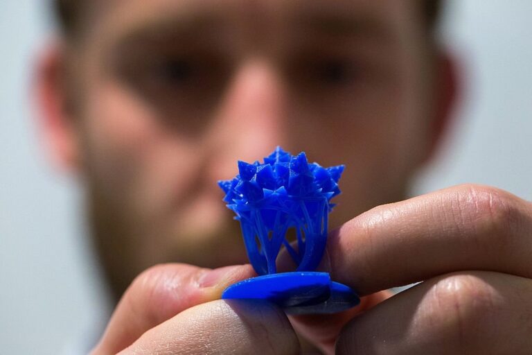
It suited vat photopolymerization 3d printing methods for producing detailed items with flawless surface finishes. Surgical learning tools, face prostheses, and hearing aids are among the most popular uses in the medical and dentistry fields. We can make low-volume injection Molds also using vat photopolymerization.
The ingredients used in vat photopolymerization additive manufacturing differ depending on the technique.
SLA, for example, works with a variety of photopolymer resins, including conventional, strong, flexible, translucent, and castable resins. In contrast, it can only use DLP with traditional and castable resins.
Carbon DLS has its materials as well. Resins are not universal; each resin type imparts unique physical and chemical characteristics to a component. Engineers and product teams should always establish their project requirements before evaluating prospective materials against them.
vat photopolymerization additive manufacturing most commonly used resins
| Material | Characteristics |
|---|---|
| Standard resin | + Smooth surface finish – Relatively brittle |
| High detail resin | + Higher dimensionally accuracy – Higher price |
| Clear resin | + Transparent material – Requires post-processing for a very clear finish |
| Castable resin | + Used for creating mold patterns + Low ash percentage after burnout |
| Tough or Durable resin | + ABS-like or PP-like mechanical properties – Low thermal resistance |
| High-temperature resin | + Temperature resistance + Used for injection molding and thermoforming tooling |
| Dental resin | + Biocompatible+ High abrasion resistant- High cost |
| Flexible resin | + Rubber-like material- Lower dimensional accuracy |
Advantages and disadvantages of vat photopolymerization
Advantages
vat photopolymerization additive manufacturing has remained popular among manufacturers because it is excellent for making complex components and is faster than other production techniques in terms of pure volume. High build quantities are possible using vat photopolymerization devices. Improvements in quality, speed, and printed part size have accelerated the commercial viability of these technologies.
- High precision and a good surface finish
- Relatively rapid procedure
- Typically, large build zones
disadvantages
The physical limitations of various vat photopolymerization-compatible materials have been the fundamental constraint of SLA and DLP technologies. We did not recognize UV curable resins for their strength, durability, or stability, except for a few robust and hard resins. These resins can warp and distort over time, change color, and require a long post-curing period to provide sufficient strength. With more stable materials, the Carbon DLS method overcomes these flaws. DLS creates components with isotropic qualities that are stronger and more durable.
- Expensive in comparison
- extended time for Post-processing and resin removal
- narrow use for Photo-resins materials
- Support structures and post-curing are frequently required for sections to be robust enough for structural application.
Reference
- dreams.mii.vt.edu
- fastradius.com
- materflow.com
- lboro.ac.uk
- hubs.com