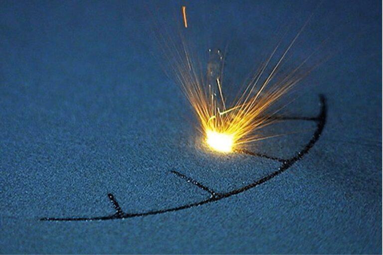
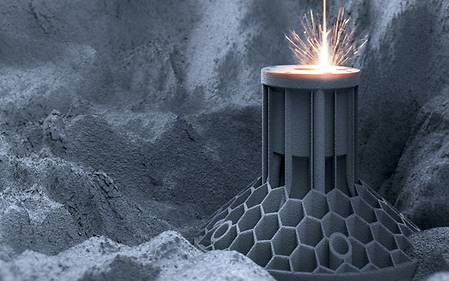
Powder Bed Fusion is a popular method for producing 3D printed parts. The process uses a high-powered laser to sinter powdered material into the desired shape. Typically, powder manufacturing companies made this powder from plastics and metals, although it can also include ceramics, glass, and other materials.
Powder Bed Fusion process
Direct metal laser sintering, Electron beam melting, Selective heat sintering (SHS), Selective laser melting (SLM), and Selective laser sintering(SLS) are all part of the Powder Bed Fusion process. These technics used to make many types of things.
A laser or an electron beam can melt and fuse the material powder in a powder bed fusion (PBF) method. Electron beam melting (EBM) methods need a vacuum to work, but we can use these technologies to make functional parts out of metals and alloys. All PBF processes involve spreading the powder material over the layers before it. There are many ways to do this, like with a roller or a blade.
A hopper or a reservoir is below or next to the bed and brings in new material. Direct metal laser sintering (DMLS) is the same as SLS but with metals instead of plastics used in the process. When heated, the powder solidifies into a single part. It’s different from other processes because it uses a heated thermal print head to fuse the powder. It added layers using a roller between fused layers, just like before. A platform lowers the model so that it fits.
PBF History
Selective laser melting was one of many proprietary powder bed fusion technologies in 1995 at the Fraunhofer Institute ILT in Aachen, Germany. A German research project led to the so-called basic ILT SLM patent DE 19649865, called the “basic ILT SLM patent.” Dr. Dieter Schwarze and Dr. Matthias Fockele from F&S Stereolithographytechnik GmbH in Paderborn, Germany, worked with ILT researchers Dr. Wilhelm Meiners and Dr. Konrad Wissenbach right from the start of the process. In the early 2000s, F&S started a business relationship with MCP HEK GmbH, which later changed its name to MTT Technology GmbH and SLM Solutions GmbH. The headquarters of the corporation are in Lübeck, in northern Germany. This company is where Dr. Dieter Schwarze works now, and Dr. Matthias Fockele started “Realizer.”
ASTM International’s F42 standards committee has put selective laser melting in the same category as “laser sintering.” This idea is a mistake because selective laser melting completely melts the metal into a solid homogeneous mass, unlike selective laser sintering (SLS), which is an exact sintering process. Among other things, we know selective laser melting as direct metal laser sintering or DMLS. The EOS brand gave this term to the method, which is deceptive because throughout This process does not sinter the parts. This term means the part is fully dense. When people talk about SLM processes, we often think of this one as an SLM process.
EBM history
There is also electron beam melting (EBM), which uses an electron beam as the power source.
SLS, SLM, and EBM are the three leading technologies to fuse the powder. These came from work done at the University of Texas at Austin in the early 1980s. In 1989, EBM patented. it made SLM and DMLS in Germany part of a project between the Fraunhofer Institute and other groups In 1995. In 1997, Arcam AB, a company in Sweden, made EBM into a real business. Arcam AB sold its first machine in 2001 and shipped it in 2002. They invented HSS in the UK in 2003, and it looks like it could be a new type of AM.
Step-by-Step Powder Bed Fusion
- A thin layer of material, approximately 0.1mm thick, applies to the build platform..
- A laser fuses the model’s initial layer, or cross-section
- A roller distributes a new coating of powder over the preceding one.
- Additional cross-sections or layers are fused and added.
- It repeats the technique until the model is complete. The loose, unfused powder remains in place during post-processing, eliminating the unused powder.
12 steps to final part
- They are turned into cross-sections of objects and saved as files called Stl, which can make 3D objects. Find out what a.stl file is and other acronyms and abbreviations used in 3D printing by going to this page.
- They loaded parts into the printer through a user interface.It then moved this stereolithographic file into place in the correct orientation. In the future, this could be software that you use to run on your computer or to print.
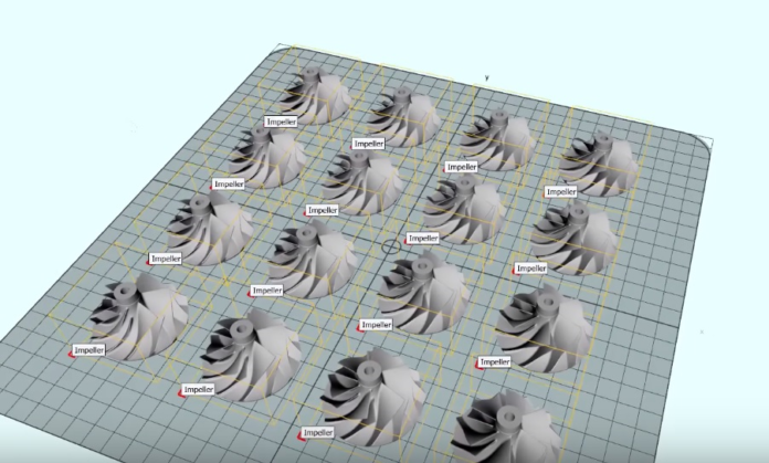
- The image below shows We can fill the build area with many different parts to speed things up.
- Hand can do it or by a machine. We then filled the powder chamber with powdered build materials (material in powder form). Powder filling could be through a build material cartridge or a hopper.
continue
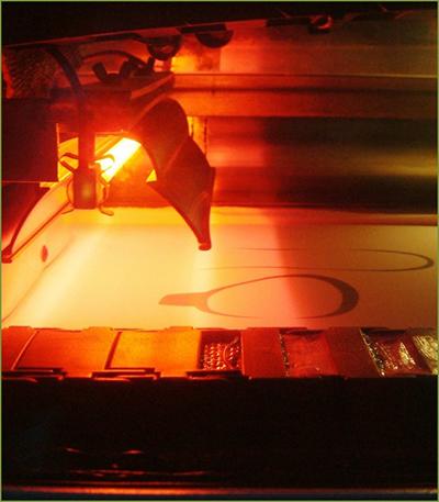
- After that, a roller spreads the powder on the build platform. Because the layer is so thick, it determines how well each part looks.
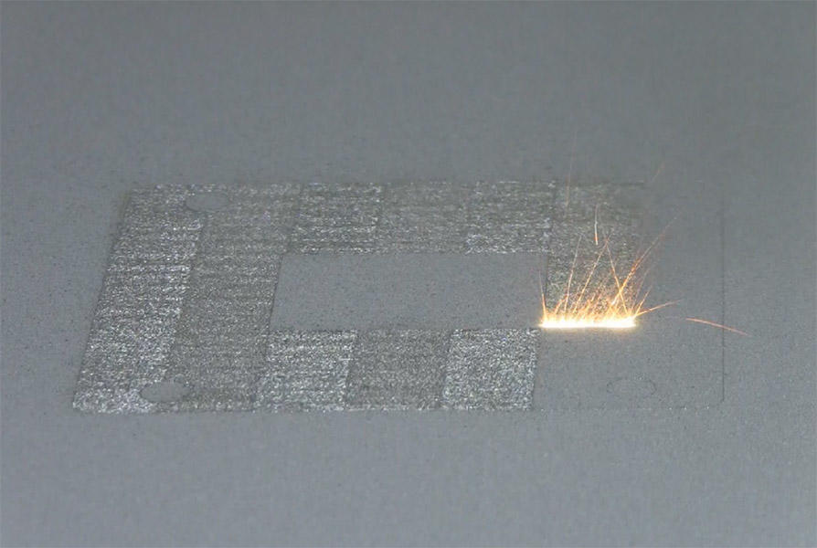
- A laser or electron beam melts the metal powder deposited on the surface. It deposits powder by looking at digital 2D cross-sectional data in the STL file.
- When that layer is scanned and fused, the bed z-axis, which is how far down the build platform can go, lowers the build platform. The machine raises the powder chamber at the same time.
- A roller then spreads a thin layer of powder across the build chamber or platform on top of the fused part of a layer thickness rolled into the powder.
- After scanning and melting another layer, the energy source does it all over again. This process keeps going until it did the 3D object being built.
- When the print job finishes, the part will be buried in the powder build chamber at the end. As shown in the picture below, we will remove the powder, but the fused part will stay attached to the build plate as shown.
- Remove parts from the build plate by using wire eroding or other tools. As a result, it’s essential to ensure that the parts are designed and loaded in the right way so that they don’t get mixed up and there’s less waste.
- Depending on the size of the machine, the chambers can be separate cartridges or built-in hoppers that we can replace.
PBF technologies
Powder Bed Fusion can also be known as
- Direct Metal Laser Remelting or DMLR
- Electron Beam Additive Manufacturing or EBAM
- Direct Metal Laser Sintering or DMLS® (EOS GmbH)
- Direct Metal Printing or DMP (3D Systems Corporation)
- Electron Beam Melting or EBM (Arcam AB)
- High Speed Sintering or HSS
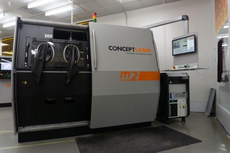
- LaserCUSING® (Concept Laser GmbH)
- Selective Electron Beam Melting or SEBM
- Micro Laser Sintering or MLS (EOS GmbH)
- Selective Heat Sintering or SHS
- Selective Laser Melting or SLM
- Laser Metal Fusion (TRUMPF Laser Technology)
- Selective Laser Sintering or SLS® (3D Systems Corporation)
Selective laser sintering (SLS)
SLS machines include three parts (Gibson et al., 2010): a heat source to fuse the material, a means to manage the heat source, and a mechanism to add new layers of material over the old. Because the powder material provides appropriate model support throughout the build process, the SLS technique does not require any extra support structures. The build platform is enclosed in a temperature-controlled chamber with a temperature a few degrees below the material’s melting point, decreasing the need for the laser to fuse layers. The chamber is frequently filled with nitrogen to maximize oxidation and the model’s final quality. Models must be allowed to cool down to obtain high tolerance and fusion quality. Specific machines track temperature layer by layer and adjust the laser’s power and wattage accordingly to increase the rate.
Selective Laser Melting (SLM)
Laser Melting with a Specific Focus (SLM) SLM is generally quicker than SLS (Gibson et al., 2010); however, it needs an inert gas, has more significant energy expenditures, and often has a 10 to 20% energy efficiency (Gibson et al., 2010). A roller or a blade is used to disperse new layers of powder over previous ones. When a blade is a sed, the machine often vibrates the blade to evenly distribute the powder (Gibson et al., 2010). A hopper or reservoir supplies fresh material beneath or beside the bed.
Selective Heat Sintering (SHS)
Selective Heat Sintering (SHS) employs a heated thermal printhead to fuse powder material. This method benefits from using a thermal print head instead of a laser because it dramatically reduces the amount of heat and power required. Thermoplastic granules are employed as support material, as they have been in the past. The ‘Blue printer’ is a desktop SHS 3D printer with a build chamber of 200mm x 160mm x 140mm, a print speed of 2-3mm/hour, and a layer thickness of 0.1mm (Blue Printer SHS, 2014).
Direct Metal Laser Sintering (DMLS)
Direct Metal Laser Sintering (DMLS) is similar to SLS; however, it employs metals instead of plastic particles. Various technical metals are accessible, and the procedure sinters the powder layer by layer.
Electron Beam Melting (EBM)
Layers are fused to melt metal particles using Electron Beam Melting (EBM). Electromagnetic coils and a vacuum pressure of 110-5 Mpa was employed to regulate the beam by machine maker Arcam (EBM Arcam, 2014). Due to a uniform temperature distribution during fusion, EBM delivers models with excellent strength attributes (Chua et al., 2010). The process’s exceptional quality and finish make it ideal for producing high-grade parts for aircraft and medical devices. The technology has several advantages over typical implant manufacturing processes, including creating hip stem prostheses (Agaruala, 1995). Using EBM with titanium and a layer thickness of 0.1mm, as opposed to CNC machining, can produce better results in less time and save up to 35% on costs.
Powder Bed Fusion Post Processing
Removal of superfluous powder, cleaning, and CNC work is part of the post-processing process. Increased density and hence structural strength of a component is one advantage and specific goal of post-processing. To get a more consistent microstructure, you can use a process called liquid phase sintering to melt metal powders or powder combinations and mix them. However, shrinkage must be taken into account because the material will shrink. Another approach for increasing density is hot isotactic pressing, which involves applying high pressures and temperatures to the material in a vacuum-sealed chamber. Although this is an excellent way to increase strength, it takes longer and costs more money.
A lot of the time, parts made with powder bed fusion need to be post-processed before being used in their intended applications: this is especially true for metals and alloys. For example, this might happen because of the following:
- Improve the strength of things (via heat treatment)
- Minimize residual stress (such as through heat treatment)
- Using chemical or laser polishing and abrasive grit blasting, you can improve the surface finish of a part.
PBF Materials
With SLM machines, you can work with a space of 1m (39.37 in) in all three directions simultaneously. Some of the materials used in this process are Ni-based superalloys, copper, aluminum, stainless steel, tool steel, cobalt chrome, titanium, and tungsten. SLM is an excellent way to make tungsten parts because this metal has a high melting point and a high ductile-brittle transition point. It broke many materials down into small pieces (powder form). They usually made these powders from gas atomized prealloys, which is the most cost-effective way to make spherical powders on a large scale.
spherical powder
The goal is for the powder to be spherical because it will have a high flowability and packing density, which means it will spread quickly and evenly. To improve flowability, even more, grains with a small percentage of small particles like 15 – 45 m or 20 – 63 m are used. 17-4 and 15-5 stainless steel, maraging steel, cobalt-chromium, Inconel 625 and 718, aluminum, AlSi10Mg, and titanium Ti6Al4V are some of the alloys that can be used in the process right now. Samples made with direct metal laser sintering have different mechanical properties than those made with casting.
AlSiMg samples made with direct metal laser sintering have a higher yield engineering than those made with commercial as-cast A360.0 alloy by 43% when built on the XY-plane and 36% when built on the z-plane. If you build AlSiMg, There is proof that its yield strength increases in both the XY-plane and the z-plane. The elongation at break decreases in that direction. Because the direct metal laser sintering samples now have a very fine microstructure, they have better strength.
DMLM
You use direct metal laser melting (DMLM) to make a new additive. We made the beds so that the powder could melt right before it built the surface. In addition, more superalloy powders, like AM108, have been added to the processing options because of industry pressure. A lot more goes into making a piece of metal than just printing it and orienting it. It also needs to be heated and hammered after printing to make it stronger and durable. Additive printed Ni-based superalloys are usually minor bend and break than wrought or cast materials.
The data comes from Tokyo Metropolitan University’s research. The directionality of the print, as well as the grain size, are essential. In addition, wear properties are usually better because of the surface condition, as shown in the studies done on the additive Inconel 718. The study also showed that laser power affected density and microstructure. During laser processing, the density of the material can also affect how cracks behave. When the density is higher, crack reopening after the HIP process is less likely. It is essential to have a clear picture of the material and how it will be used so that you can figure out its mechanical properties for design.
Advantages of Powder Bed Fusion
This process has a lot to do with the properties of the materials. It’s possible to make things like nylon, copper, and even ceramics out of many different kinds of materials. Next, completely or partially melted parts can be stronger than non-melted parts. This topic is because the material properties can be very close to the stock material. It may not need structures that hold things up in some cases because the powder bed acts as a support. Build speeds can also be very fast, depending on the materials and the process.
Processes that warm the powder bed to just below melting are the fastest because they allow a breakneck scan speed. They’re the quickest process because no moving parts can move the beam. People who use lasers make things with a lot of detail and small features. EBM can work with very reactive materials to oxygen, so it can make things faster and cheaper than subtractive methods.
Disadvantages of Powder Bed Fusion
Many of these processes can only use one type of material in the end. Some methods need inert gases as an extra material to use. In comparison to other techniques, layer heights rely on the size of each particle of powder; hence they have a poor resolution in the build direction. The roughness of EBM’s surface finish necessitates post-processing smoothing to satisfy highly tight tolerances.
Some methods need different support structures to be removed from the final part by hand. EBM needs more than an air blast to remove unsolidified material because the remaining powder no longer moves like a light metal powder but clings together like wet sand. To get rid of the powder, you’ll need to utilize powder blasting, ultrasonic vibration, or mechanical means, with some geometries like deep, narrow cavities making it even more challenging to get rid of the powder,
Application
We can use laser melting for many different things, but it’s best for things with complicated shapes and structures with thin walls that hide voids or channels or small lot sizes on the one hand. We can make both solid and not yet formed objects in some cases. For example, a hip stem or acetabular cup can be made with a surface that helps osseointegration. We have done most of the early work with selective laser melting technologies on lightweight parts for aerospace, where traditional manufacturing constraints, like tools and physical access to surfaces for machining, limit the design of parts. SLM lets us make parts almost as good as possible if we use only the right amount of material to make them.
Traditional manufacturing methods require a lot of money to set up and get going (e.g., creating a mold). SLM has a high price per part because it takes a lot of time. If only a few parts need, use SLM. Many parts of old machines (like cars from the 1950s) and individual items, like implants, must be kept separate.
NASA tests
Results from tests done by NASA’s Marshall Space Flight Center, which is using the technique to make parts for the J-2X and RS-25 rocket engines, show that parts made this way are a little weaker than parts made by forging and milling, but they don’t need to be welded, which are weak points.
We use this technology to make direct parts for various industries, including aerospace, dental, medical, and other industries that produce small to medium-sized, complex parts. We also used it in the tooling industry to make direct tooling inserts. DMLS is a great way to save money and time. Production manufacturing as well as quick prototyping both make use of this technology. It shortens the time it takes to create new products and saves money by reducing the number of parts and complex geometries that need to be put together. When it comes to a standard build envelope (e.g., for EOS’s EOS M 290), it is 250 x 250 x 325 mm. It can also “grow” multiple parts at the same time.
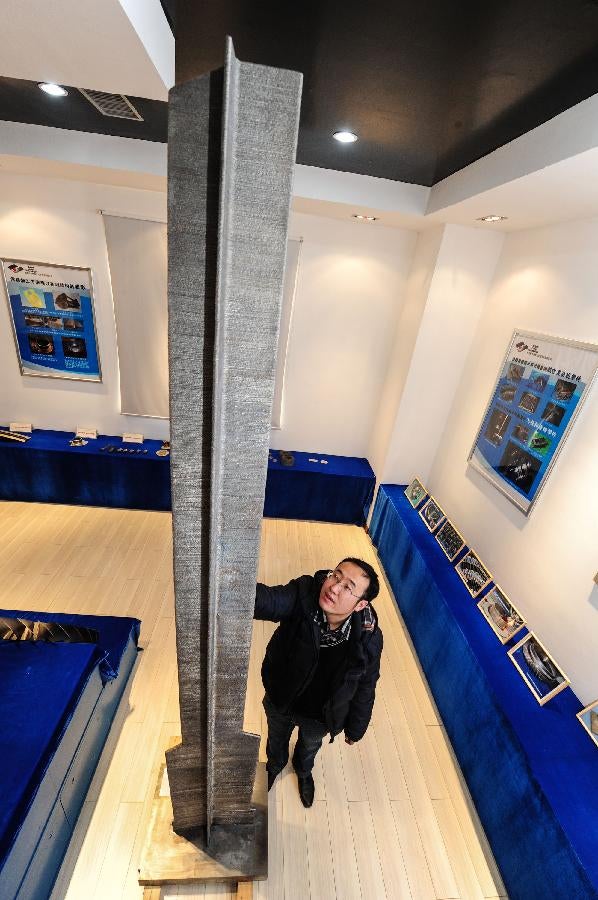
The photo below is how the Northwestern Polytechnical University of China makes structural titanium parts for airplanes. According to research by EADS, the use of the technology in aircraft applications would reduce material and waste consumption.
SpaceX
On September 5, 2013, Elon Musk tweeted a picture of SpaceX’s regeneratively-cooled SuperDraco rocket engine chamber coming out of an EOS 3D metal printer. He said we made it off the Inconel superalloy, which is very strong. In a surprise move, SpaceX said in May 2014 that we had built the first fully printed rocket engine. The SuperDraco engine is the first to be built this way. Direct metal laser made Inconel, an alloy of nickel and iron, sintering. The engine runs at a high pressure of 6,900 kilopascals (1,000 psi) and a very high temperature. The engines are inside a printed protective nacelle, which is also DMLS-printed, to keep faults from spreading if one of the engines fails. In May 2014, the engine passed a full qualification test. There are plans to make its first orbital space flight in April of 2018.
Complex cooling channels
The ability to 3D print the parts made the low-mass goal of the engine possible. According to Elon Musk, there are many things that people don’t know. “Complex: It was hard to make all the cooling channels, the injector head, and the throttling mechanism by hand. Making the SuperDraco engine possible was very important to be able to print solid, advanced alloys that could be used to make it work.” They made the parts for the SuperDraco engine with a 3D printer, which dramatically shortens the time it takes to make them. They also have better strength, ductility, and fracture resistance, with minor variations in materials properties.
In 2018, the FDA approved the first-ever 3D printed titanium spine implant made with SLM.
Industry applications
Aerospace
Laser-sintering is suitable for both commercial and military aerospace. This method can make air ducts, fixtures, or mountings that hold specific aeronautic instruments.
Manufacturing
Laser-sintering can serve niche markets with low volumes at a low cost. Laser-sintering doesn’t have to think about batch size optimization because it doesn’t depend on economies of scale.
Medical
There are a lot of complicated and high-value products in the medical field. They have to meet the needs of the customer exactly. These rules don’t just come from the operator’s personal preferences. They also have to be followed by people who live in different parts. This Variety leads to many different types and small amounts of available variants.
Prototyping
Laser-sintering can assist in prototyping by producing functional design and functional prototypes. So functional testing may start quickly and easily. At the same time, We can use these prototypes to see if people will like them.
Tooling
The direct process doesn’t need to make a tool path or use other machining processes, like EDM. We can make them overnight or even in a few hours. Also, the freedom of design can be used to improve the performance of a tool, for example, by putting cooling channels inside the tool.
Other applications
These parts have cavities, undercuts, and draft angles in them.
Models that fit, look and work.
The tools, fixtures, and jigs
It’s called “conformal cooling.”
Rotors and impellers are the parts that move the air.
As you can see, the brackets are very complicated.
FAQ
Powder bed fusion (PBF) is an additive manufacturing technology that operates on the same fundamental idea as milling in that objects are made by adding material rather than deleting it.
Powder bed fusion has several benefits, some of which are described here. Reduced material waste — Most of the waste associated with subtractive manufacturing technology is avoided by layering the part together. When the part is finished, any extra powder is collected and recycled.
Selective Laser Sintering (SLS)
Selective Laser Melting (SLM)
Direct Metal Laser Sintering (DMLS)
Electron Beam Melting (EBM)
Powder bed fusion (PBF) technologies melt and fuse material powder using either a laser or an electron beam. The employment of a heated thermal print head to fuse powder material distinguishes Selective Heat Sintering from other techniques. As previously, layers are applied with a roller between the fusion of layers.
Refrence
- wikipedia.org
- youtube.com
- nist.gov
- lboro.ac.uk
- canadamakes.ca
- zdnet.com
- engineeringproductdesign.com
- us.dmgmori.com