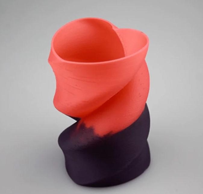
Material Extrusion for 3D Printing
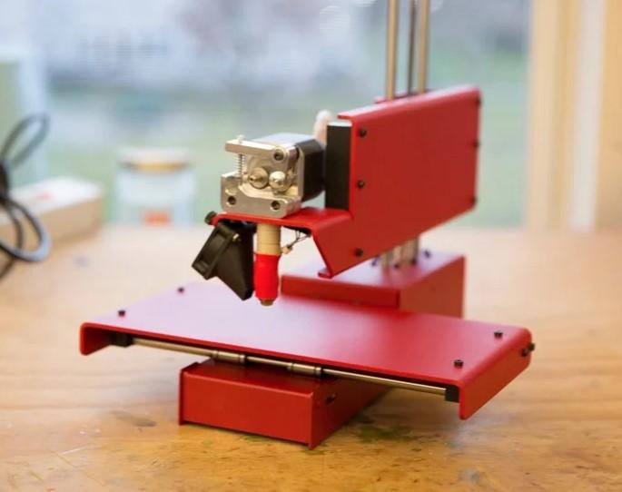
Material Extrusion 3D Printing (also known as Fused Filament Fabrication or Fused Deposition Modeling) is a 3D printing method that uses thermoplastic filament to build three-dimensional objects. The filament is molten and driven out of the nozzle after being fed from a big coil through a moving, heated print head (extruder). The material is then deposited on the developing workpiece using a computer-controlled nozzle. It uses computer-controlled nozzle motions.
History
All additive manufacturing processes that put the material through a nozzle are extrusion-based. Scott Crump created and patented the first industrial material extrusion technique in 1989. Crump is a co-founder of Stratasys, the firm that brought fused deposition modeling (FDM) as the second additive manufacturing method to the market in 1991.
How Does It Work?
You can use 3-D printing to create models from a wide variety of materials such as composite. A print head – where the nozzle is – may move around while depositing the material, drawing a 2D layer in this fashion. Once the substance hardens, whether by cooling or drying, it can be difficult to remove.
After that, the print head increases to deposit the next layer of extruded material on top of the previous one. It does the layer-by-layer deposition method until it obtains the required 3D object. The plastics extrusion is, without a doubt, the most generally associated procedure with desktop FDM 3D printing.
Process
- The nozzle linked to the printer deposits material directly onto the build platform.
- It applies the following layers on top of the preceding layers. The printhead goes up while the build platform remains fixed.
- It fused the layers upon deposition.
The process’s variations
Hot extrusion of rods
Instead of a filament, the feedstock in this 3D printing equipment is a rod shape. Because the rods are thicker than the filaments, it may be more efficient to push them towards the hot end of a FFF 3D printer. on the other hand, Filaments are thinner than the rods they slide through, so they move faster and generate more pressure than in a traditional extruder.
Cold extrusion of slurries
The feedstock for these 3D printing machines is a mixture of solids and liquids that, once deposited, hardens. As a general rule, a piston moves materials towards the nozzle. In this case, the nozzle will not get hot. The fused filament method with a custom paste extruder can make ceramics and chocolate.
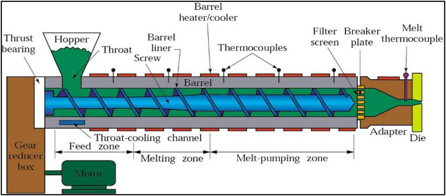
Hot extrusion of pellets
Pellets, i.e., tiny grains of thermoplastic material or combinations of the thermoplastic binder with powder fillers, are fed into these sorts of 3d printing machines by hot extrusion. A piston or a revolving screw pushes the material towards the nozzle enclosed within an extrusion barrel. The
The process’s physics
Mechanical pressure from rollers melts and extrudes the thermoplastic filament into the liquefier. The portion considers the extruder’s flow shape, the heating process, and the melt flow behavior of a non-Newtonian fluid. Because the rollers are the only driving mechanism in the material delivery system, the filament is tensile upstream of the roller and compressed downstream, functioning as a plunger. As a result, compressive stress propels the extrusion process.
For the melted material extruding, the force must be adequate to overcome the pressure drop throughout the system, determined by the viscous characteristics of the melted material and the liquefier and nozzle flow geometry. Melted materials undergo shearing while they’re in a state of flow. For instance, many of the materials in this exhibit have a property called shear thinning. When modeling general Newtonian fluids, physicists use a power law.
Heat input from electrical coil heaters regulates the temperature. The system forms a negative feedback loop by continually adjusting the power provided to the coils based on the temperature difference between the target value and the value observed by the thermocouple. This system is analogous to a room’s ambient heating.
Printing process
The FFF method begins with a software operation that mathematically slices and aligns an STL file (STereoLithography file format) in preparation for the building process. It may create support structures if necessary.
A mechanical stage moves the nozzle in the XY plane and can carry it horizontally and vertically.
The steps in the process include a 3D Printer Extruder, deposited material (modeled part), and a controlled moveable table.
When the nozzle passes over the table, it can extrude a material called “Roads”. Roads hardens when it comes into contact with the substrate and previous roads.. We deposit roads side by side inside an enveloping domain border, and we create solid layers by following a rasterizing motion.
extrusion head moves
Stepper motors or servo motors usually move the extrusion head. Although alternative mechanical designs, such as delta bot. The most common mechanism used in robotics is a three-axis rectilinear design.
Once a layer is complete, the platform moves down in the Z direction a bit to start building the next layer. It repeats this procedure until the object’s construction is complete.
Controlling the heat environment is crucial for good road bonding in the process. The system keeps its temperature at a low temperature of below the material’s melting point within a chamber.
flexible printing process
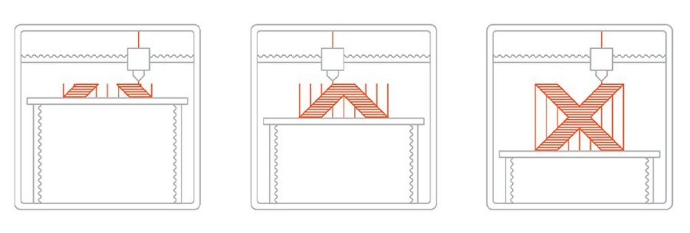
Although FFF is a very flexible printing process that can deal with little overhangs by using support from lower layers, it has certain limitations on the slope of the overhang and cannot make unsupported stalactites.
Acrylonitrile Butadiene Styrene (ABS), Polylactic acid (PLA), Polycarbonate (PC), Polyamide (PA), Polystyrene (PS), lignin, rubber, and many more materials are available, each with differing strength and temperature qualities. Furthermore, the color of a thermoplastic substance might impact the printed object’s strength. For the first time, a German company demonstrated the technological possibility of turning granular PEEK into filament and 3D printing items from the filament material using FFF technology.
It exposed the hot molten polymer to air during FFF. Operating the FFF process in an inert gas environment, such as nitrogen or argon, improves layer adhesion and improves the mechanical qualities of the 3D printed products. They use an inert gas during selective laser sintering to keep the powder from oxidizing.
Kinematics of the print head
They built the majority of fused filament printers in the same way. For the print workpiece, it employed a flatbed as the starting point. A gantry above this carries the movable print head. The print bed moves on three axes, with most of the movement occurring along the X and Y axes. Prints gradually develop as they move up along the Z axis. Leadscrews or toothed belt drives move the movement of stepper motors. Because of the disparities in movement speed, toothed it commonly used belts for the X, Y drives and a leadscrew for the Z drive. The gantry can move the X-axis on some machines, but you still have to move the bed (and print job) for the Y-axis. Because head movement rates are modest compared to laser cutters, stepper motors are widely employed, and servomotors are not required.
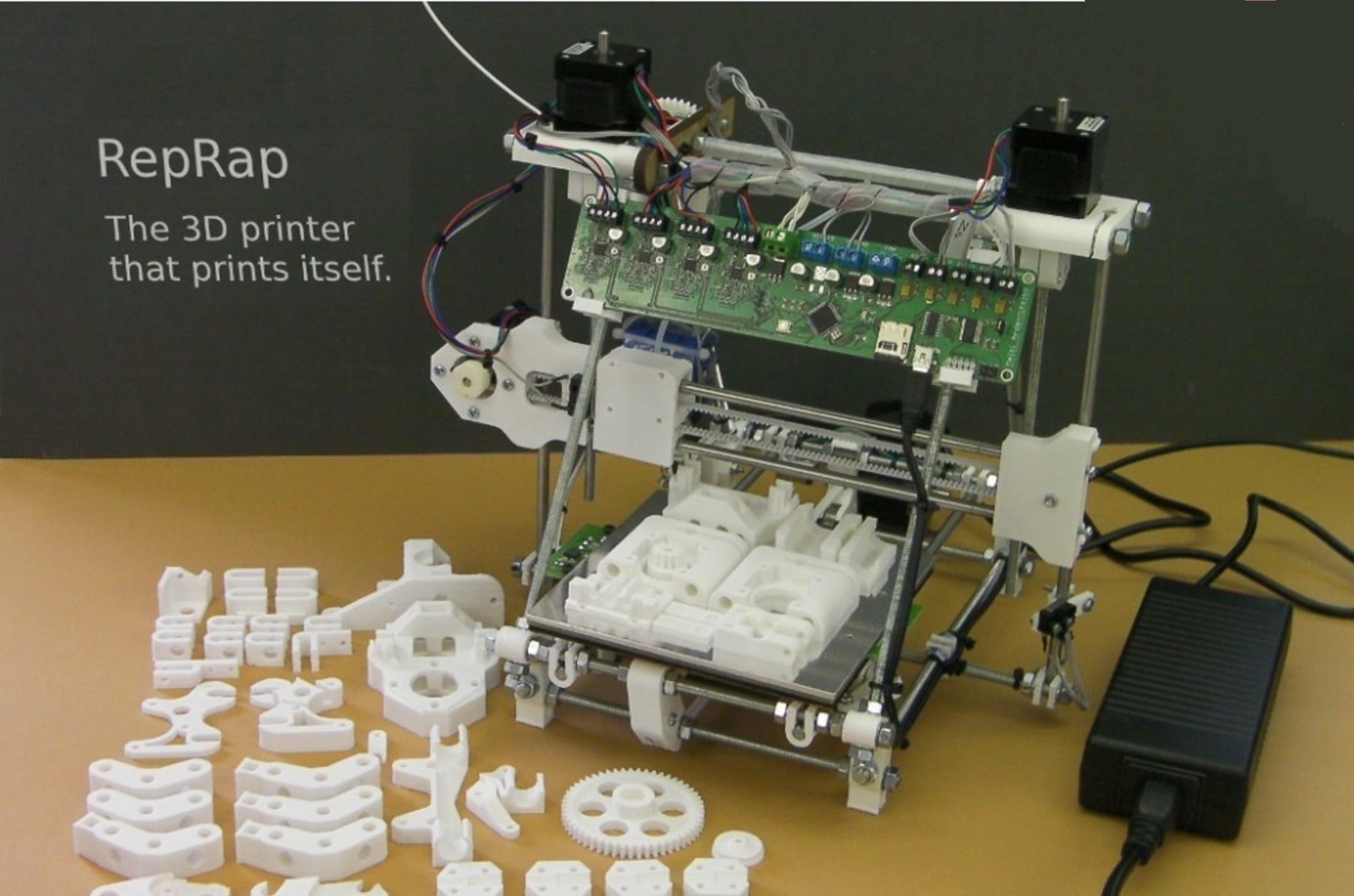
RepRap project
Many printers, particularly those inspired by the RepRap project, employ 3D printed components extensively in their creation. Printed connection blocks with various angled holes are frequently used, with inexpensive steel threaded rods connecting them. This results in a low-cost, simple-to-assemble structure that allows for non-perpendicular frame connections, although it does need the use of a 3D printer. The idea of ‘bootstrapping’ 3D printers in this way has become a fundamental element in the RepRap designs. The lack of rigidity in the rod necessitates either triangulation or the danger of a flexing and vibrating gantry frame in service, lowering print quality.
Many modern machines have semi-enclosed frames made of laser-cut plywood, plastic, pressed steel sheets, and, more recently, aluminum extrusions. These are inexpensive, sturdy, and may also be utilized as the foundation for an enclosed print volume with temperature control to prevent print job warping.
polar coordinate
Only a few machines, mainly those designed to print structures with circular symmetry, employ polar coordinates instead. These have a revolving bed and a radial gantry movement. Although this design for printing hollow cylinders has some potential mechanical advantages, its unique shape and the resulting non-mainstream approach to print planning have kept it from becoming used. Although converting from Cartesian to polar coordinates is a simple operation for a robot’s motion planning, receiving any benefit from this design needs the print slicing algorithms to be aware of the rotational symmetry from the start.
Post process
It’s important to address and improve the surface integrity of parts made by AM before more businesses use this technology (Jamiolahmadi and Barari, 2014). The staircase effect comes from the layer-based nature of the AM process family. This staircase effect makes the surface rough. The thickness of the layers is the most important thing that affects the staircase effect. A thinner layer makes the surface rougher, but it takes longer to build. Another thing that can weaken the surface integrity of parts made by some AM processes, like Fused Deposition Modelling (FDM), is the need for support material where there is no material beneath the current layer.
The interaction between the support material and the built material causes the roughness of the built material. This interaction makes it hard to remove the support material and adds more money and time to the process. FDM is one of the AM processes with bad surface roughness and needs much support. Layer thickness, part orientation, raster angle, road width, And so on are some things that can be changed when making the map. Armillota et al. (1999), Sood et al. (2009), and other people have looked at the surface roughness of AM parts and talked about what factors make it rough.
layer thickness affect on part surface
The curvature of a product’s surface can determine which layer thickness is best for it. You can figure out how thick a layer should be by looking at how it curves on the surface. Choose the thickness of each layer by looking at how the surface is curved (Mani et al. 1999, Pandey et al. 2003, Sikder et al. 2015). We call this adaptive cutting. It doesn’t matter how many changes you make to AM parts. The surface roughness of the parts still needs to be better. FDM parts, in particular, need more work. Post-processing makes the surface of the parts smoother. They thought that the build orientation was the primary factor contributing to the roughness of the surface, and they wanted to minimize post-processing work.
two types of post-processing
There are two types of post-processing: mechanical and chemical. Kulkarni and Dutta (2000) said that CNC machining could help improve the surface roughness of FDM parts. This study looked at how to make tool paths. Boschetto et al. (2016) also used CNC machining for this, and They added variable cutting depths proportional to the angle of deposition.
Other people have said that adding mechanical methods to the process can make the surface smoother (William and Melton, 1998, Leong et al., 1998, Pandey et al., 2003). Mechanical processes have some drawbacks, including the inability to access some parts of the surface, the parts being fragile, the costs of the process, and the need to clamp the part.
Mechanical post processing
Boschetto and Bottini used Barrel Finishing (BF) in 2015, which did not need clamping. Build orientation is the most important design factor in this method, and the BF working time is the most important process factor that affects the final surface roughness. It takes longer to process, which leads to better results. This mechanical method doesn’t meet the needs of a practical method from the 12th IFAC Workshop on Intelligent Manufacturing Systems because there are still places this process can’t get to, and delicate parts could be damaged.
This means that an effective method must improve the surface roughness without changing the surface’s mechanical and geometrical properties, improve the surface roughness over the entire surface, and not require clamping and other costly operations. Using chemicals can affect the surface roughness without following the same rules as mechanical methods.
Chimical post processing
However, some chemicals, such as acetone, might not be good for building materials like Polylactic acid (PLA) because they don’t mix. If you want to finish the parts made of Acrylonitrile Butadiene Styrene, acetone is a good way to do it (ABS). There was a big difference in the surface roughness of the ABS parts after it chemically cleaned them with acetone in 2014 and 2009, and 2010. There was no change in the prototype’s dimensions.
Kuo and Mao (2016) said that it took less time to smooth. It took longer to smooth if there was more surface area. Garg et al. (2016) looked at the effect of part orientation on the surface roughness of parts heated in an acetone vapor bath. They found a considerable reduction in the staircase effect.
post-processing parameters
We have not talked about the process parameters in these studies. There is no connection between the post-processing stage and the roughness of the surface.There hasn’t been much discussion about producing a rough surface in previous investigations.The literature review shows that chemical methods are better than mechanical ones. So, this study aims to look into the post-processing parameters that affect the surface roughness and come up with a straightforward way to figure out the final surface roughness based on the post-processing setups.
Because the specimens in this study do not need to be supported by anything, this impact is not considered. This study has much roughness because of how the FDM process works. After making an FDM part, we can use the results of this study as design models for the next parts. By examining how rough a surface is, you may determine the best time to expose it to acetone vapor.
Fused Deposition Modelling (FDM)
S. Scott Crump is the guy behind the FDM technology’s creation. The technique was created and patented in the 1980s. Crump later founded Stratasys in 1988 and patented the phrase “Fused Deposition Modelling.”
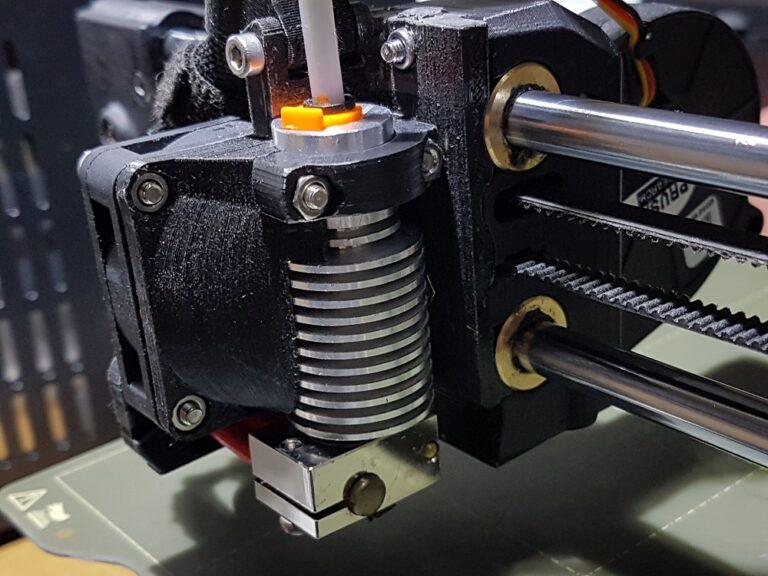
FDM is an extrusion method with a hot end and a cold end. The hot end is an extrusion head that receives fabrication material by unwinding a coil of plastic filament or metal wire. A worm drive feeds the wire or filament to the head’s nozzle at a regulated pace. The filament or wire is heated past the glass transition temperature when it reaches the extrusion nozzle and melts.
When molten filament or wire exits the extrusion nozzle, it hardens instantly on a base or onto a preceding layer, depending on whether we expose it to air or an inert gas chamber. The usage of inert gas chambers increases because it increases layer adhesion by preventing oxidation and improves the mechanical properties of the manufactured item.
It mNylonve the extrusion nozzle horizontally and vertically while moving the base platform along the remaining third plane.
numerical mechanism
A numerical mechanism controls the nozzle’s vertical and horizontal movement, while a tool-path generated by computer-assisted manufacturing (CAM) software determines its movement along the third plane. The nozzle travels from bottom to top, depositions each layer after another, or remains fixed with the moving platform. Finally, the nozzle moves rectilinearly in an XYZ plane guided by stepper motors. Deltabot hasNylonessfully attempted to shift the nozzle end using current advances.
Models are often produced in FDM using a variety of thermoplastics, and something generates their support structures concurrently. The support structures are required to maintain the model during the procedure. The materials utilized to construct support structures are soluble in their respective environments. Acrylonitrile Butadiene Styrene (ABS) and Polylactic acid are the two most prevalent thermoplastics used in FDM (PLA). Other polymers utilized include polyamide (PA), lignin, polycarbonate (PC), polystyrene (PS), rubber, and several conductive compounds.
Fused Filament Fabrication (FFF)
Fused Filament Fabrication is a phrase established by the RepRap project, an open-source effort dedicated to creating low-cost and economical desktop 3D printers. This community-driven effort provides 3D printers that are Free and Open Source Hardware (FOSH). The RepRap project’s successful efforts have made it possible to build 3D printers that used to cost at least $20,000 for $1000 or less.
The method of Fused Filament Fabrication is nearly identical to that of Fused Deposition Modelling, except words used to identify distinct parts of the 3D printer and names for process specifications. The process of melting the feedstock and depositing a layer of the molten material is known as “Liquefier.” The areas where these layers are built up in a three-dimensional form are called “Roads.” It precisely maintained the thermal environment of the chamber in most FFF printers to a temperature that is only slightly lower than the material’s glass transition temperature.
extruder layout in FFF 3D printers
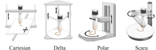
Cartesian-XY
The liquefier and nozzle’s motion is tied to the X-Y axis, and the platform on which it produced the model lowers (Z-axis) as a layer successfully rasterizes on the X-Y plane. RepRap’s first 3D printer, Darwin, is of the Cartesian-XY kind.
Cartesian-XZ
In this design, the extruder head travels in the X and Z axes while the platform moves left and right along the Y-axis. As a result, the platform can manage the additional load. The Mendel is the first Cartesian-XZ type 3D printer built on Arduino from the RepRap project. RepRap Guru DIY Prusa I3 3D Printer and Original Prusa i3 3D are two more popular Cartesian-XZ FFF printers.
Delta
This design is similarly a Cartesian setup, but it supports the extruder head by three triangle arms dangling in the air. This configuration provides for improved precision and quicker printing. Afinibot Micro Delta Kit, Folger Tech Kossel Auto Leveling Delta 3D Printer Kit, He 3D – Mega Delta 3D Printer Kit, Rostock MAX v3, and more low-cost Delta 3D printers are available.
CoreXY
This Cartesian extruder head setup is an improvement over the traditional XY configuration. Instead of sequential X-Y movement, CoreXY allows the head to move using a parallel system of x and y coordinates. RepRap-XY by “jand,” C-bot, AluXY by “Zelogik,” Vulcanus, AXIOM 20 Direct Drive, VSlot-CoreXY, and Voron are some examples of CoreXY 3D printers.
Polar
The extruder head rotates left or vertically up and down on each right-side transition using a polar head arrangement, creating the object on a spinning circular platform.
SCARA
The acronym SCARA stands for Selective Compliant Assembly/Articulated Robot Arm. The extruder head travels along all axes in a Cartesian fashion (X, Y, and Z)
The difference between Cartesian and Polar printers
Three or four Stepper motors are used in Cartesian FFF printers to move the head in X, Y, and Z-axis, whereas just two stepper motors, are used in Polar printers.
advantages of Material Extrusion 3D Printing
Material Extrusion 3D printing opens up new options for part designs. It allows engineers to realize plans with closed holes, undercuts, and other geometries that would be hard to fabricate with traditional manufacturing processes. Parts of diverse sizes and forms, which previously required several tool changes and stresses, may now be created in one piece without the need for further interventions using Material Extrusion 3D printing. Material extrusion is appropriate for more expensive materials due to nearly nil production-based material waste.
Disadvantages of Material Extrusion
Because Material Extrusion 3D printing works by depositing molten material in a layer-by-layer way, it creates more complicated geometries than any other manufacturing method. However, there are certain inherent process limits. Geometries such as steep overhangs and bridges may be challenging to build with Material Extrusion.
Pros and Cons
Pros
- Broad process
- Lower cost equipment makes this procedure available to a larger audience.
- ABS plastic is a popular, commonly available material that has strong structural qualities
- The machine is easier to operate.
- It is possible to print from a cloud server.
- Customers may select from various materials, and they can tailor printers to meet their needs.
- FDM 3D printers are also easy to repair.
Cons
- The nozzle radius restricts and decreases the ultimate quality.
- In comparison to other methods, precision and speed are lacking.
- It restricted the precision of the final model to material nozzle thickness.
- The continual pressure of material is essential to boost the quality of the finish.
- There is much troubleshooting.
- When printing for lengthy periods, the nozzle might clog.
- Long print time
- In comparison to other 3D printing procedures, the prints are weaker.
- Adhesion issues between layers are a regular occurrence.
- Compared to SLA and SLS, layers are visible, and intricate patterns are challenging to print accurately.
Materials
Technically, any material that can be forced through a nozzle while maintaining its form, whether heated or not, maybe utilized for material extrusion procedures. Plastic, concrete, clay, bioink, and consumables like chocolate are examples of this.
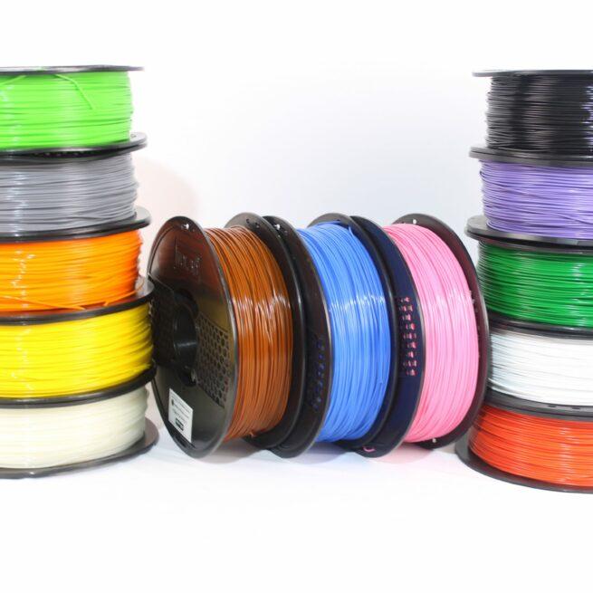
Pure or composite thermoplastics in filament form are without a doubt the most often utilized extrusion material. Most thermoplastics, from standard industrial plastics like ABS and nylon to more high-end engineering materials like PEEK, are appropriate for this technique. Composite materials such as metal- or carbon-fiber-filled polymers are also options for highly specialized tasks.
Polymers and plastics are examples of materials. Polycarbonate is an example of a polymer (PC). The most common material for material extrusion is thermoplastics. Acrylonitrile Butadiene Styrene (ABS), Polylactic Acid (PLA), High-Impact Polystyrene (HIPS), Thermoplastic PolyUrethane (TPU), aliphatic PolyAmides (PA, often known as Nylon), PolyEther Ether Ketone (PEEK), and PolyEtherimide are some examples of thermoplastics (PEI).
Filament manufacturing process
The filament is the main component of the FDM process. We typically construct the filament of a pure polymer with a low melting point. We must increase the strength of the pure polymer in some circumstances. As a result, several academics and enterprises have produced polymer composites as 3D printing filament materials by combining the matrix and strengthening the components to achieve systems with structural qualities and functional benefits that are impossible to accomplish with just one ingredient.
Commercially available filaments consisting of pure polymers may be treated directly as FDM material. However, because each reinforcement in a composite polymer has various properties, manufacturing composite filaments must first be treated differently.
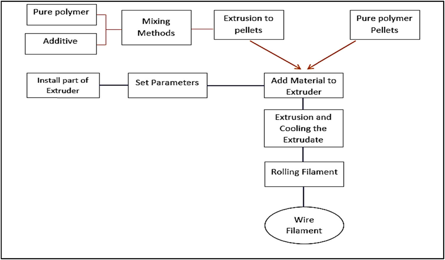
Extruding pellets or raw materials from polymers can create pure polymer filament for FDM products. We use extruders in this process, which pushes or presses the material through perforations in the die to produce an extrudate.
strengthen the filament
There are other ways to strengthen the filament, like combining the materials before extruding them and making each composition ready to be integrated. Depending on the qualities of the elements, it can blend the materials in various ways. We can finish it either by mixing the solution and drying it before extracting it or using the dry mixing technique. The most common use of this method is for mixing polymer filament material, which involves swirling a pure polymer in a stirring machine with spinning rollerblades at the polymer’s melting point temperature.
The additives are then applied in stages according to the needed proportion following the compatibilizer procedure. It usually takes 30 minutes. The molten material is then allowed to cool to room temperature to ensure homogeneity. It can process the resulting mixture into pellets or small pieces of fabric, ranging from 2 to 4 mm, and then extruded.
Several factors influence the filament during the extrusion process. The filament cable diameter is affected by die temperature, roller puller speed, spindle speed, and intake temperature. Because the settings in this process impact the material’s viscosity, the material’s output is extruded at the nozzle die rather than the target diameter. The winding screw form, on the other hand, has an impact on the filament’s regularity. The thread form will affect the direction of the filler employed in the filament, especially in composite filaments.
production of filament phases
The production of filament using an extrusion machine involves many phases. The first stage involves:
- Calculating the filament diameter to be produced.
- Setting up the extrusion settings.
- Adding the material as a pellet.
- Extruding from the nozzle die hole until wrapped around the roller machine.
Most common Filament types
It classified polymer filament into two types based on its composition: pure polymer filament and composite filament. The pure polymer filament is produced wholly of a polymer compound without using additional solutions. Each form of pure polymer filament has its unique mechanical properties and features. Even yet, the inherent characteristics of pure polymers may not always accommodate the mechanical qualities required for some goods.
This difficulty necessitates that academics and businesses produce polymer filaments acceptable for commercial use. Adding additives to the filament composition is one of the ways to improve the mechanical qualities of a filament. It created the composite filament as a result of this technique. We employ some pure polymer filaments that it was often used in 3D printing and development procedures in the following.
PLA
Researchers have produced PLA, one of the most innovative materials for various applications. This type of polymer is biodegradable and thermoplastic. We can use PLA in medicinal applications because of its biocompatibility and lack of metabolic toxicity and We may accomplish this by converting it into a filament and then using the FDM technique to treat it. We can then transform the filament into a variety of implantable shapes and developed a PLA/graphene oxide (GO) nanocomposite material with a customizable structure using FDM’s 3D printing scaffolding process.
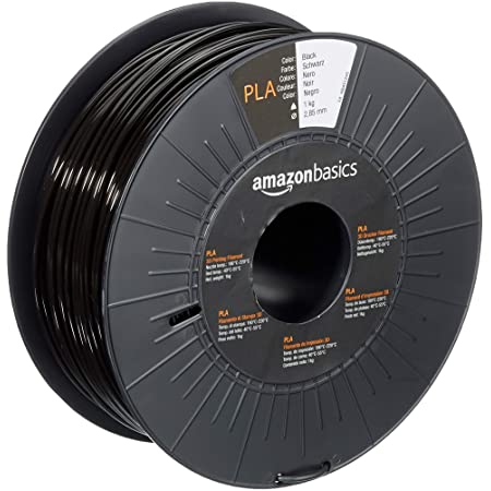
When we make bone, we can use a 3D-printable PLA/GO nanocomposite that is safe for cells and has good mechanical properties. We have tested PLA-based filaments to enhance their mechanical qualities, starting with pure PLA, thermoplastic elastomeric thermoplastic (TPU) mixes, and E-glass fiber-reinforced composites (GF). These studies show that using GF as a fiber-reinforced material is helpful since it increases tensile and flexural modulus. PLA mixes get robustness with including TPU.
ABS
We use this word to describe a lot of different acrylonitrile blends and copolymers, butadiene-based polymers, and styrene. Styrene–acrylonitrile (SAN) copolymers were popular in the 1950s, but ABS was a better choice because it was less likely to break down. We mixed ABS with SAN or nitrile rubber for further improvement. Because nitrile is soft, the room temperature makes this structure an amorphous, glassy, tough, and impact-resistant material that is also strong and durable.
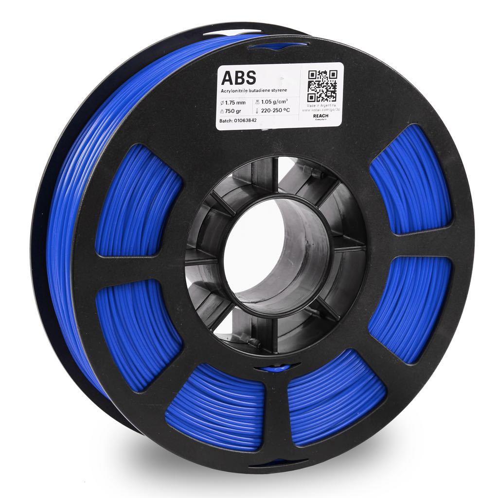
Acrylonitrile Butadiene Styrene has a lot of different compositions and effects of additives, which makes it worse in some ways. ABS is the most common material used in the FDM method for 3D printing because it is easy to work. Still, the choice of other ingredients has its flaws. Researchers came up with several ways to improve the mechanical properties of ABS, one of which was to make an ABS composite filament that was reinforced with GO by adding two wt % GO to it, made with solvents. This method worked well when printing the filament ABS into a 3D model. ABS can be made more robust and more flexible by adding GO.
PP
PP is a homopolymer belonging to the polyolefin family. It is one of the most common low-density and low-cost thermoplastic semicrystals used in everyday clothes and shoes. PP’s physical and chemical properties make it a good choice for many industries, such as the military or making cars. However, PP has poor thermal, electrical, and mechanical properties compared to other engineering plastics like PC, PA, Etc. It also has a high coefficient of friction in dry shear conditions, which makes it hard to work.
They add nanoparticles of inorganic filler to PP to make it more durable. Yetgin (2019) looked at how adding GO to PP, with and without maleic-anhydride-grafted polypropylene (PP-g-MA) as a compatibilizer agent, changed the properties of the plastic. They used extrusion and injection processes to do this. With more weight and speed, the friction and wear rate of PP nanocomposites go up. The coefficient of friction is 74.7 percent lower than the pushing speed.
Another study compared polypropylene (PP) ‘s printing abilities filled with 30% glass fiber to polypropylene that they don’t fill with glass fiber. In terms of mechanical properties, they tried to do this. There is a 40% increase in the modulus and ultimate tensile strength when added glass fibers. The researchers have done much research on how to better make 3D-printed PP filled with cellulose nanofibrils and make compounds with spherical microspheres for FDM printing that make it easier to print and make compounds with spherical microspheres that make them more durable. The optimized system had impact energies about 80% higher than pure PP in a final impact test on printed composites.
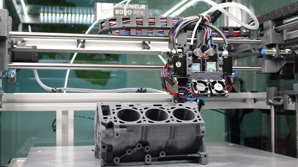
Composite Printing
The availability of composite fabrication became conceivable when it became possible to equip a 3D printer with numerous extruders to speed up the fabrication process or enable multi-material capabilities. One of these is Composite Filament Fabrication (CFF). Markforged created the phrase, which refers to the usage of two print nozzles. One nozzle uses the standard material extrusion method to lay down a plastic filament that produces the part’s outer shell and interior matrix.
second nozzle
The second nozzle covered every layer with a continuous strand of composite fiber (made of carbon, fiberglass, or Kevlar). These straight strands of composite fibers inside 3D printed parts offer strength to the manufactured thing that is equivalent to claims made of metal. Aside from employing composite materials for vital components, the layering approach can impact part strength. Markforged distinguishes between two fiberfill strategies: isotropic and concentric fiberfill.
we 3D printed Even composites on machines with only one extruder with material extrusion. The only need is that the base material (a thermoplastic) be present in sufficient amounts to ensure that the layers fuse. Wood 3D printing (wood particles embedded in PLA), metal 3D printing (metal particles embedded in thermoplastic), and even carbon 3D printing (carbon fibers embedded in thermoplastic) were all made possible by combining two materials in a single thread.
Typical Applications
Material extrusion is a pretty simple procedure. Besides support structure(s) removal and superficial polishing, the raw material is usually easy to handle, and the completed product doesn’t require much post-processing. The removal of support structure(s) creates an ideal setting for fast prototyping, the most prevalent FDM-like methods.
We use material extrusion methods in hundreds of industrial applications. Concrete extrusion machines may construct structures, and Researchers have already used innovative bioprinting techniques to manufacture human tissues and organs.
Fabrication of jigs and fixtures is also beneficial to material extrusion. Leading automobile corporations such as Volkswagen and BMW manufacture manufacturing help devices for their vehicle assembly lines regularly because of the comparatively low cost of components.
Refrence
- https://apiumtec.com/en/material-extrusion-fff-3d-printing
- https://www.plm.automation.siemens.com/global/ko/our-story/glossary/material-extrusion/53981
- https://www.engineersgarage.com/3d-printing-processes-material-extrusion-part-2-8/
- http://yifeijin.org/material-extrusion/
- https://all3dp.com/2/main-types-additive-manufacturing/
- https://www.3dhubs.com/knowledge-base/introduction-fdm-3d-printing/
- https://make.3dexperience.3ds.com/processes/material-extrusion
- https://www.azom.com/news.aspx?newsID=57817
- https://en.wikipedia.org/wiki/Fused_filament_fabrication
- https://theprojectfaction.com/ultimate-guide-on-fused-deposition-modelling-fdm-3d-printing/
- https://www.degruyter.com/document/doi/10.1515/eng-2021-0063/html
- https://www.amazon.de/AmazonBasics-3D-Drucker-Filament-PLA-Kunststoff-Wei%C3%9F-1-kg-Spule/dp/B07RZTF5QF
- https://shop3duniverse.com/products/kodak-abs-filament-1-75mm-750g#v12144986554468
- https://www.sciencedirect.com/science/article/pii/S2405896316328300
- https://zortrax.com/post-processing/apoller/
- https://www.sciencedirect.com/science/article/abs/pii/S0924224421000844